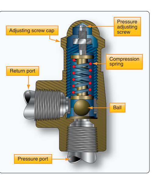
Every hydraulic system aboard an aircraft operates within a carefully defined pressure range. When something goes wrong — a pump overspeeds, a selector valve is left closed, or hot fluid expands inside a sealed line — system pressure can climb far beyond design limits in seconds. Without protection, hoses burst, fittings blow out, actuators rupture, and the entire hydraulic circuit can be rendered useless at exactly the moment a pilot needs it most. Two unsung heroes stand guard against these scenarios: the pressure relief valve (PRV) and the thermal relief valve (TRV). Understanding how each works, where each is installed, and how to inspect them is core knowledge for any airframe technician and a regular subject on the AMT Airframe knowledge test.
What Is a Pressure Relief Valve?
A pressure relief valve is a normally-closed, pressure-sensitive valve whose job is to limit the maximum operating pressure of an entire hydraulic system or a specific circuit within it. It is sometimes called a system relief valve when protecting the main circuit, or a circuit relief valve when protecting a branch such as the landing gear or flight control circuit.
Inside the valve body, a steel ball or poppet is held against a precisely machined seat by a calibrated spring. As long as system pressure stays below the set point, the spring force keeps the poppet sealed and no fluid passes through the valve. When pressure reaches the cracking pressure — the threshold at which the valve just begins to open — hydraulic fluid pushes past the poppet and is routed back to the reservoir through a return line. This venting action prevents further pressure rise. Once pressure drops back below the set point, the spring reseats the poppet and normal operation resumes. The entire event can happen in a fraction of a second and may repeat rapidly if the root cause (such as a continuously running pump with no open actuator) is not corrected.
The system relief valve is typically set about 10–15 percent above the normal operating pressure to allow a small safety margin without interfering with normal operations. For example, if a system is designed to operate at 3,000 psi, its system relief valve might be set at roughly 3,300–3,500 psi. These exact values are specified in the aircraft's maintenance manual and must never be changed arbitrarily. An improperly adjusted PRV set too low will vent continuously during normal operation, wasting pump energy and overheating the fluid. One set too high provides inadequate protection and can allow dangerous over-pressurization.
What Is a Thermal Relief Valve?
A thermal relief valve addresses a completely different threat: thermal expansion of trapped hydraulic fluid. Hydraulic fluid expands as it warms. When fluid is trapped between a closed selector valve, a locked actuator, and a section of metal tubing — with no path back to the reservoir — even a modest temperature rise can create enormous pressure increases because hydraulic fluid is nearly incompressible. On a hot ramp, or when hot engine bleed air or brake heat warms a sealed line, pressure in that trapped section can rise hundreds or even thousands of psi above the relief setting of the main PRV, which cannot help because it is upstream in the system.
The thermal relief valve is installed locally within the trapped section — often directly in the line supplying an actuator, a brake assembly, or adjacent to a selector valve — so it can vent that localized pressure spike. Like the system PRV, it is a spring-loaded poppet valve. However, it is typically set at a lower differential pressure than the main system relief valve and is sized to pass only the small volume of fluid generated by thermal expansion, not the full pump flow. Once the excess pressure is relieved, the TRV reseats.
Thermal relief valves are commonly found protecting:
- Brake assemblies, where heavy braking followed by aircraft parking can trap very hot fluid
- Flight control actuator circuits that may be isolated for long periods
- Any segment of tubing that passes through a high-temperature environment (near engines or APUs)
- Retracted landing gear bays where aerodynamic heating can warm isolated lines
Why These Valves Matter
The consequences of PRV or TRV failure are serious and directly affect airworthiness. A failed-open PRV means the system cannot build or sustain operating pressure, leaving flight controls, brakes, nose wheel steering, or other hydraulically powered systems inoperative. A failed-closed PRV — or one that is stuck shut — means there is no protection against overpressure, risking catastrophic component failure. A failed TRV in a brake line can allow thermal expansion to apply the brakes when the aircraft is parked or even while airborne after gear retraction, causing brake dragging, fire risk, or structural damage to the wheel well.
From a maintenance standpoint, relief valves also serve as diagnostic indicators. If a system PRV is dumping fluid continuously during normal operation, it signals that either the pump pressure regulator has failed, the accumulator is not functioning, or a selector valve has been left in the wrong position. The technician should never simply adjust the PRV upward to stop the venting without first determining and correcting the root cause.
Key Numbers and Rules
- System relief valves are set above normal operating pressure, typically 10–15% higher, per the aircraft maintenance manual.
- Thermal relief valves are set to protect localized segments from thermally-induced pressure; they pass only small flow volumes.
- Both valves are normally closed and open only when pressure exceeds their set point.
- Relief valves bypass fluid back to the reservoir (system PRVs) or to the return line (circuit/thermal relief valves) — they do not vent overboard.
- Set-point adjustment, if allowed at all, must be done only according to manufacturer specifications using calibrated test equipment.
- After any relief valve replacement or adjustment, a system pressure check must be performed to verify proper cracking pressure and full-flow relief.
- Thermal relief valves must be verified for proper seating after testing; a valve that does not reseat will cause system pressure loss.
Inspection and Testing Considerations
During scheduled maintenance, the technician inspects relief valves for external leakage past the seat or body seals, which shows up as wet spots or staining on adjacent lines and components. A PRV that is weeping fluid even at normal system pressure indicates a worn seat or contaminated poppet and must be replaced or overhauled. Contaminated hydraulic fluid is one of the most common causes of valve seat damage; grit or metallic particles can prevent the poppet from fully seating, leading to constant low-level bypass and system pressure instability.
Functional testing typically involves pressurizing the system with a hydraulic test stand and slowly raising pressure while monitoring the gauge. The cracking pressure — when the valve first opens — and the full-flow relief pressure are recorded and compared against maintenance manual limits. Some valves have an external adjustment screw protected by a locknut and safety wire; others are factory-set and non-adjustable, requiring replacement if out of tolerance. Always safety-wire adjusting screws and lock nuts after any setting change to prevent inadvertent movement from vibration.
Thermal relief valves in brake assemblies deserve special attention after rejected takeoffs or hard braking events. Heat soak into the brake assembly can cause the TRV to lift and discharge fluid. The technician should inspect for fluid around the valve fitting, check brake fluid levels in the reservoir, and verify the valve reseats properly before returning the aircraft to service.
Common Test Traps
- PRV vs. TRV purpose confusion: The system PRV limits maximum pump output pressure; the TRV relieves thermal expansion in isolated, trapped sections. They are not interchangeable in function or location.
- Where fluid goes: Relief valves route fluid back to the reservoir or return line — they do not dump fluid overboard. Students sometimes confuse them with vent valves or drain valves.
- Normally-open vs. normally-closed: Both relief valves are normally closed. They open only on overpressure. Do not confuse them with pressure-reducing valves or sequence valves, which operate differently.
- Adjusting the PRV to stop venting: A common test scenario presents a system that is continuously relieving. The correct action is to find and fix the root cause, not simply raise the PRV setting — doing so would leave the system unprotected.
- Thermal relief valve location: The TRV must be installed within the trapped volume it protects. A TRV on the pump outlet cannot relieve pressure in a locked actuator line downstream of a closed selector valve.