Knowing exactly how much fuel an aircraft carries is a fundamental safety requirement. Run out of fuel in flight and the outcome is predictable and grim. Yet fuel quantity indicating systems are among the most commonly misunderstood and misread instruments in general aviation. For the Aviation Maintenance Technician (AMT) working on airframe systems, a thorough command of how float-type, capacitance, and sight-glass fuel gauges work — and how each can fail — is both an exam requirement and a professional obligation.
This article covers the operating principles of all three major system types, the regulatory requirements that govern them, maintenance considerations, and the failure modes that can produce dangerously misleading readings. By the end, you should be able to explain each system from first principles, recognize common faults during inspection, and answer the most commonly tested AMT knowledge-test questions with confidence.
Regulatory Foundation
Before diving into system mechanics, it helps to anchor everything in the regulations. 14 CFR Part 23 (airworthiness standards for normal-category airplanes) requires that each fuel tank have a means to indicate the quantity of usable fuel in the tank. Critically, the regulations require only that the gauge read accurately at the empty (zero usable fuel) position — not necessarily at intermediate points. This is a frequently tested fact: a fuel gauge that reads inaccurately at mid-tank but reads correctly at empty still meets the minimum certification standard. This does not mean inaccurate gauges are acceptable in practice — it means the AMT must understand what the certification baseline actually is.
Float-Type (Resistor/Rheostat) Systems
How the system works
The most common fuel quantity system on light general-aviation aircraft is the float-type resistive sender. A cork or foam float rides on the fuel surface, connected by a mechanical arm to a variable resistor (rheostat) mounted at the tank. As fuel level drops, the float arm rotates, moving the wiper across the resistor coil and changing the electrical resistance in the circuit.
This variable resistance signal is sent to the cockpit gauge — either a ratiometric (d'Arsonval movement) meter or a direct-reading indicator. In a simple resistive system, the gauge pointer deflects in proportion to the current flowing through the circuit, which is inversely proportional to the resistance. The exact wiring convention is manufacturer-specific: some designs use low resistance to represent a full tank and high resistance to represent empty, while others are wired the opposite way. The AMT must always consult the aircraft's approved maintenance data for the specific sender and indicator combination rather than assume a single universal convention.
Power dependency and failure modes
Float-type systems require electrical power to operate. On the common design in which loss of current mimics the empty-tank (high-resistance) condition, a total loss of electrical power or an open circuit will cause the gauge to read empty rather than falsely full. This is an important safety characteristic on that design: the failure mode defaults toward a warning rather than a falsely optimistic reading. However, because wiring conventions vary by manufacturer, the AMT must verify the specific failure behavior for the system being serviced using the aircraft's maintenance manual rather than assume it applies universally.
Common faults in float-type systems include: a stuck or corroded float arm that no longer rotates freely; a broken or worn rheostat creating an open circuit or an erratic reading; fuel contamination or deposits on the sender unit that impede float travel; and tank sump leaks that cause the sender unit to sit in a partial vacuum. The AMT should always compare the indicated quantity against a direct measurement (dipstick or visual check) when troubleshooting a suspected sender discrepancy.
Compensation and calibration
Float-arm systems are calibrated to a specific tank shape. Because most aircraft fuel tanks are irregularly shaped (conforming to the wing contour), the relationship between float angle and actual fuel volume is nonlinear. Manufacturers compensate for this by shaping the rheostat resistance curve or by physically bending the float arm to specific angles recorded in the maintenance manual. Any time a sender unit is replaced, the AMT must verify calibration per the aircraft's approved data — typically by filling the tank to known quantities and checking indicator readings at each point.
Capacitance-Type Fuel Quantity Systems
Operating principle
Capacitance fuel quantity systems are standard on turbine-powered aircraft and high-performance twins, and they are fundamentally more accurate than float-type systems. Rather than measuring a mechanical position, they measure a dielectric property of what is inside the tank.
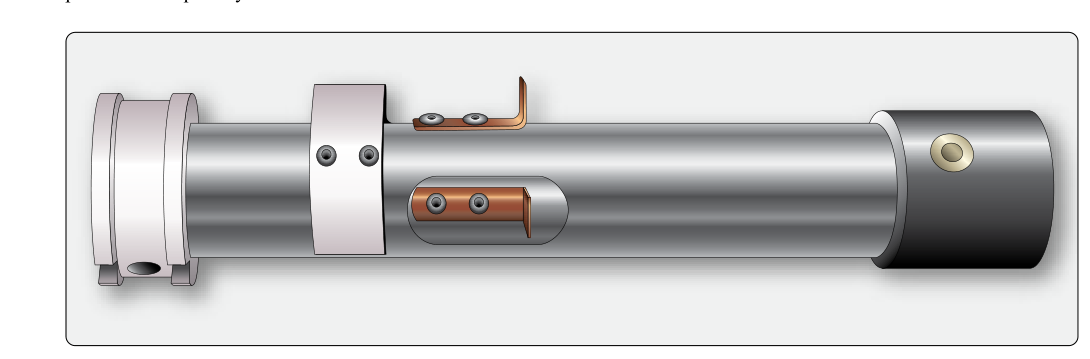
A capacitor consists of two conductive plates separated by an insulating material (dielectric). The system installs capacitor probes (tank units) vertically inside the fuel tank — essentially two concentric aluminum tubes. When the tank is full of fuel, the fuel acts as the dielectric between the tubes; when empty, air is the dielectric. Jet fuel has a dielectric constant of approximately 2.0–2.2, while air has a dielectric constant of approximately 1.0. As fuel level changes, the proportion of fuel versus air between the plates changes, altering the capacitance of the probe.
A signal conditioner or bridge circuit translates the capacitance value into a fuel quantity reading on the cockpit indicator. Because the system responds to the dielectric property of the liquid — not just its level — it can also account for fuel density changes caused by temperature if a compensator (reference) unit is installed. The reference unit remains fully submerged at all times; its capacitance reading reflects only the current dielectric constant of the fuel. The processing unit computes true fuel mass (or volume corrected for density) by comparing tank units against the reference unit.
Advantages over float systems
Capacitance systems offer several important advantages: no moving parts in the tank (improving reliability and reducing maintenance), multi-probe configurations that account for fuel distribution across large or oddly shaped tanks, and the potential for mass-based readouts rather than just volume — which is especially valuable for turbine operations where fuel burn is computed in pounds per hour.
Failure modes and troubleshooting
The most common fault in a capacitance system is a shorted or open probe, often caused by fuel contamination, water intrusion, or corrosion on the probe connectors. A shorted probe typically drives the indicator to full-scale; an open probe typically drives it to zero. Because these failures can mimic genuine tank states, the AMT must verify actual fuel quantity independently before relying on any indication. Mixing fuel types (such as accidentally adding aviation gasoline to a kerosene system) also changes the dielectric constant of the fuel, producing inaccurate readings — another reason proper fuel identification and quality control matters.
Calibration of a capacitance system requires specialized equipment — typically a capacitance bridge or dedicated test set — and must follow the aircraft manufacturer's procedures. Disturbing probe wiring or adding unapproved coatings inside a tank can shift calibration significantly.
Sight Gauges
A sight gauge is the simplest possible fuel quantity indicator: a transparent tube or window connected to the tank that allows direct visual observation of the fuel level. Sight gauges are common on small light-sport aircraft, experimental aircraft, and certain gravity-feed systems. Some are merely a clear standpipe beside the tank; others are molded windows in the tank wall itself.
The principal advantage of a sight gauge is independence from any electrical system. The reading cannot be affected by an electrical failure, a bad sender, or a corroded connector. What you see is what is in the tank — provided the gauge itself is not contaminated or occluded.
Maintenance concerns for sight gauges center on sealing integrity and material degradation. The transparent material (typically a fuel-compatible plastic or glass) can yellow, craze, or crack over time, making accurate reading difficult. Fittings and hose connections must be inspected for leaks, since a failed sight-gauge fitting introduces both a fuel-quantity error and a fire hazard. The AMT should also verify that the sight gauge lines are free of air locks or vapor pockets that could produce a falsely high reading.
Why These Systems Matter to the AMT
Fuel quantity errors are a direct contributor to fuel exhaustion accidents. The AMT plays a critical preventive role by ensuring sender units are correctly installed and calibrated, probe connections are clean and sealed, gauges are properly bonded electrically, and sight gauge materials are within serviceable condition. Post-repair functional checks must always include a comparison of indicated quantity against a known physical measurement.
During annual or progressive inspections, it is not sufficient to simply power the gauge and see a needle move. The AMT should validate calibration at the empty position (the only FAA-mandated accuracy point) and document any known discrepancy in the aircraft records so the pilot-in-command is informed.
Key Numbers and Rules
- Regulatory accuracy requirement: Fuel quantity gauges must read accurately at the empty (zero usable fuel) position per 14 CFR Part 23 — no accuracy mandate at intermediate readings.
- Dielectric constant of jet fuel: approximately 2.0–2.2 (air ≈ 1.0); this difference is the basis of all capacitance systems.
- Float-system failure mode: on designs where loss of current mimics the empty condition, loss of electrical power typically drives the gauge to read empty — but this behavior is design-specific, so always verify against the maintenance manual.
- Capacitance probe open fault: drives indicator toward zero (empty).
- Capacitance probe short fault: drives indicator toward full.
- Mixing fuel types in a capacitance system changes the dielectric constant and corrupts the reading.
- Sight gauge materials must be fuel-compatible and inspected for crazing, cracking, and seal integrity at each inspection interval.