Bladder fuel tanks — sometimes called flexible fuel cells or bag-type tanks — are a common design choice in general aviation, light sport, and many military-derived aircraft. Unlike rigid metal tanks that are integral to the wing structure, bladder tanks are self-contained flexible liners made from specially formulated rubber or synthetic elastomer compounds. They sit inside a structural cavity in the wing or fuselage and are secured by mechanical attachment points. Because fuel is inherently hazardous and because structural failure of a fuel containment system can be catastrophic, the FAA and aircraft manufacturers place rigorous requirements on the inspection, repair, and replacement of these components. For airframe technicians preparing for the FAA AMT knowledge test and for day-to-day maintenance work, a thorough understanding of bladder tank construction, deterioration modes, repair limits, and replacement procedures is indispensable.
This article covers the full lifecycle of a bladder fuel tank from an airframe maintenance perspective, grounded in guidance from the FAA's Aviation Maintenance Handbook (FAA-H-8083-31), aircraft manufacturer maintenance manuals, and relevant 14 CFR requirements.
Construction and Materials
Bladder tanks are fabricated from multi-ply laminates. The inner ply, which contacts aviation fuel, is formulated to resist the solvating action of avgas (100LL) or Jet-A fuel. Common inner-ply materials include nitrile rubber (Buna-N), neoprene, and various urethane compounds. Outer plies add mechanical strength and abrasion resistance, often using nylon or polyester fabric reinforcement. Fittings — for fuel quantity sender units, fuel outlet, fuel filler neck, vent lines, and drain valves — are bonded or mechanically fastened into the bladder at precisely located positions that correspond to ports in the surrounding airframe structure.
The surrounding cavity, often called the fuel bay or wet bay, provides the structural support that a rigid tank would inherently possess. The bladder itself is not a structural member; it is a liner. This distinction is critical because it means that any puncture, delamination, or fitting failure will result in fuel escaping into the wing structure rather than simply self-sealing. Aircraft manufacturers design the bays with drain holes to minimize pooling of leaked fuel, but fuel in the wing structure represents both a fire hazard and a potential for structural corrosion.
Inspection Procedures
Bladder tank inspections are conducted on a schedule defined by the aircraft's Type Certificate Data Sheet (TCDS), the Airworthiness Limitations section of the manufacturer's maintenance manual, or applicable Airworthiness Directives (ADs). Technicians should always consult the specific aircraft maintenance manual first, because bladder life limits, access procedures, and inspection criteria vary by make and model.
Visual and Tactile Inspection
Access to the bladder is typically gained by removing inspection panels in the wing or fuselage. Once exposed, the technician performs a thorough visual examination looking for the following discrepancies:
- Cracks and crazing: Fine surface cracks — often called crazing or alligatoring — indicate that the elastomer is oxidizing and losing plasticizer. Even minor crazing on the inner surface can progress to through-cracks.
- Delamination: Separation of the inner and outer plies produces bubbling or raised areas. Delaminated sections can peel away and enter the fuel system, potentially clogging filters or fuel controls.
- Porosity (seepage): Small fuel seeps through the tank wall without an obvious crack. Porosity is detected by wiping the surface clean, pressurizing the tank to manufacturer-specified low pressure (typically 1–3 psi), and then observing for fuel weeping. Alternatively, a nitrogen pressure-and-hold test may be specified.
- Fitting condition: All bonded or mechanically fastened fittings must be inspected for looseness, fuel staining around the fitting base, and integrity of the bonded seam. A loose fitting is a significant leak path.
- Chafing and abrasion: The exterior surface of the bladder must be inspected for wear caused by contact with the bay structure, fasteners, or debris. Chafing that reaches the reinforcement ply significantly reduces burst strength.
- Collapsed or kinked sections: Bladders that have been improperly stored or have lost internal support can develop permanent folds that crack over time.
Age and Service Life
Most manufacturers specify a calendar life limit for bladder tanks, typically ranging from 10 to 20 years, regardless of condition. This is because elastomers degrade chemically over time even when not in service. Some manufacturers additionally specify a retirement-by-date printed on the tank itself. A bladder that has reached its calendar life limit must be replaced — a visually good appearance does not override a published life limit. Technicians must record the manufacture date (often stamped on the tank) and compare it against the current date and the manufacturer's limit.
Repair Procedures and Limits
Not all bladder damage requires full replacement. Manufacturers typically publish repair procedures for minor damage, and repairs must be performed using approved materials and methods. Using unapproved adhesives, patches, or solvents can accelerate deterioration and may result in a fuel leak or contamination of the fuel supply.
Approved Patch Repairs
Small punctures, minor cuts, or isolated areas of surface crazing that have not progressed through the wall may be repairable using the manufacturer's approved patch kit. A typical patch repair involves the following steps:
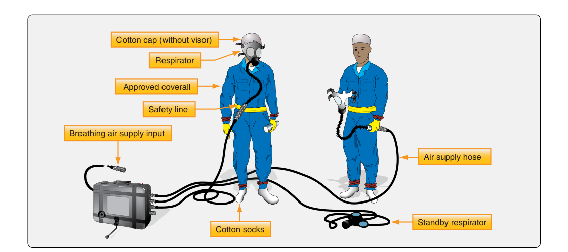
- Drain and purge the tank of fuel vapors. Ensure the tank is safe to work on — fuel vapor in a confined space is an explosion hazard. Follow all safety precautions including proper ventilation and the elimination of ignition sources.
- Clean the damaged area with a solvent approved by the tank manufacturer. Common choices include MEK (methyl ethyl ketone) or toluene, but only those specifically approved should be used, as some solvents attack the inner ply.
- Buff or lightly abrade the repair area and the patch material to promote adhesion.
- Apply the approved adhesive (cement) to both surfaces and allow it to reach the proper tack per the manufacturer's instructions.
- Apply the patch, working out air bubbles from the center outward, then apply clamping pressure or a roller to ensure full contact.
- Allow the repair to cure for the manufacturer-specified time and temperature before pressure testing.
- Perform a pressure test per the maintenance manual to confirm the repair is leak-free before reinstalling the tank.
Repair size limits vary by manufacturer but are typically expressed as a maximum patch diameter or maximum percentage of tank surface area. Multiple patches in close proximity may also be prohibited. If the damage exceeds published repair limits, or if the tank exhibits widespread crazing, delamination, or porosity over a significant area, replacement is mandatory.
Removal and Replacement
Replacing a bladder tank is a labor-intensive process that requires careful attention to parts compatibility and installation technique. The replacement tank must match the part number approved under the aircraft's type certificate; tanks are not interchangeable across models even when they appear geometrically similar, because fuel capacity, fitting locations, and material formulations may differ.
Before installing a new bladder, the technician must thoroughly inspect and clean the fuel bay. Any debris, corrosion, or protruding fastener heads that could chafe the new bladder must be addressed. Sharp edges should be smoothed and, where the manufacturer specifies, padding material (such as approved foam tape) is applied to areas of potential contact. The bay must be completely dry and free of residual old fuel or sealant material.
New bladders are typically shipped folded and must be carefully unfolded inside the bay per the manufacturer's instructions to avoid creating permanent creases. Attachment loops or snaps that secure the bladder to anchor points in the bay must all be engaged — a bladder that collapses away from its outlet fitting will cause fuel starvation. All fittings are connected and torqued to specification. After installation, a leak check at the manufacturer-specified pressure is mandatory before returning the aircraft to service. The maintenance record entry must include the new tank's part number, serial number, and manufacture date.
Key Numbers and Regulatory Considerations
- Repair pressure test: Manufacturers typically specify 1–3 psi for bladder leak tests; never exceed the published limit, as over-pressurization can damage the bladder.
- Calendar life limits: Commonly 10–20 years depending on manufacturer; always check the specific aircraft maintenance manual and any applicable ADs.
- 14 CFR Part 43: All fuel tank repairs and replacements on certificated aircraft must be performed in accordance with Part 43 and recorded in the aircraft maintenance records, including the return-to-service statement.
- Approved data: Repairs must be performed using manufacturer-approved data, an FAA-approved repair specification, or data approved under a Supplemental Type Certificate (STC). Field-improvised repairs using non-approved materials are not permissible.
- Fuel vapor safety: Before any open-tank work, the tank must be purged of vapors to a safe level. Explosimeter (combustible gas indicator) readings should confirm a safe atmosphere before any grinding, drilling, or other work that could produce sparks.
Common Test Traps
- Confusing integral and bladder tanks: Integral (wet wing) tanks are sealed cavities in the wing structure itself, not removable liners. Inspection and repair procedures differ significantly. Know which type is being discussed in any test question.
- Assuming visual condition overrides life limits: A bladder that looks perfect but has exceeded its calendar life limit must still be replaced. The FAA test may present a scenario where the tank appears serviceable — the correct answer is replacement if the life limit is exceeded.
- Using unapproved solvents or adhesives: Test questions may list repair steps and include an unapproved solvent. Recognize that only manufacturer-approved materials are permissible.
- Skipping the pressure test after repair: A pressure leak test after repair or reinstallation is not optional — it is a required step. Omitting it is an airworthiness violation.
- Ignoring bay preparation: A common mistake on the practical side (and tested conceptually) is failing to inspect and prepare the fuel bay before installing a new bladder, leading to premature chafing damage of the replacement tank.