Fuel is the lifeblood of any piston or turbine-powered aircraft, and the tank that stores it is far more than a simple container. Aviation fuel tanks must resist corrosion, handle thermal expansion, prevent leaks under vibration and maneuver loads, and remain accessible for inspection and maintenance. For the Aviation Maintenance Technician (AMT) working on airframes, understanding the three primary tank types—integral, bladder (flexible), and rigid removable—is essential for performing airworthy repairs, conducting inspections, and passing the FAA Airframe knowledge and oral exams.
Each design represents a different engineering trade-off between weight, capacity, ease of manufacture, and maintainability. This article examines how each type is built, how it works, what can go wrong, and what the FAA expects an AMT to know about keeping these systems safe.
Integral Fuel Tanks
An integral fuel tank—often called a wet wing—is not a separate vessel inserted into the structure. Instead, the aircraft's own structural cavities, typically the wing box formed by spars, ribs, and skin panels, are sealed to hold fuel directly. The fuel literally lives inside the airframe structure itself.
This design is dominant on high-performance piston singles, most jet transports, and many business aircraft. Because no separate tank envelope is needed, integral tanks offer the highest capacity-to-weight ratio of the three types. Every cubic inch of available structural space can store fuel without the weight penalty of a separate container wall.
The critical technology that makes an integral tank work is the sealant. A two-part polysulfide or similar fuel-resistant compound is applied to every seam, fastener hole, and joint inside the sealed bay. This sealant must remain flexible enough to tolerate the wing's constant bending and vibration in flight without cracking. When it fails—as it eventually will from age, thermal cycling, and flexing—the result is a structural fuel leak that can be difficult to locate and labor-intensive to repair.
Integral tank maintenance is among the most demanding tasks in airframe work. Entering a wing fuel bay to reseal it requires confined-space precautions, the complete removal of residual fuel and fuel vapors, adequate ventilation, and personal protective equipment. The FAA's Aviation Maintenance Technician Handbook—Airframe (FAA-H-8083-31) describes the procedures for cleaning, surface preparation, sealant application, and cure time that must be followed before a resealed bay is considered airworthy. Shortcuts in sealant work are a leading cause of recurring fuel leaks and can create fire hazards.
Inspection of integral tanks focuses on: detecting fuel stains on the lower wing skin (a telltale sign of seam leakage), inspecting sump drain valves for security and proper seating, checking fuel quantity sender units and their gaskets for leakage, and ensuring vent lines are open and properly routed. Access panels must be opened periodically so the interior sealant condition can be visually checked.
Bladder Tanks (Flexible Fuel Cells)
A bladder tank, also called a flexible fuel cell, is a pre-formed bag made from layers of fuel-resistant synthetic rubber or nylon-reinforced elastomeric material. It is inserted into a structural cavity—a bay in the wing or fuselage—that serves as its mechanical support, but the bladder itself is the actual fuel-tight envelope. The surrounding structure carries loads; the bladder holds fuel.
Bladder tanks are widely used in general aviation aircraft, helicopters, and military platforms. Their main advantage over integral tanks is repairability and replaceability: a leaking or damaged bladder can often be patched in the field with an approved repair kit, and when too far deteriorated, the entire cell can be removed and replaced without the intensive resealing work an integral tank demands.
Installation requires careful attention to fitting alignment. Fuel filler necks, outlets, sump drains, vent fittings, and quantity sender ports all penetrate the bladder wall through reinforced fittings. Each fitting is a potential leak point if improperly torqued or if the bladder material around it has degraded. During installation, the bladder must be positioned so it lies flat and wrinkle-free—folds or pinches in the material concentrate stress and accelerate cracking.
The most common bladder failure mode is deterioration of the elastomeric material from long-term fuel exposure, UV exposure, or simply age. Small cracks and pinholes may develop that produce slow weeping leaks, sometimes first noticed as a persistent fuel odor in the cabin rather than a visible stain. Another failure mode unique to bladder tanks is collapse: if the vent system becomes blocked, the fuel pump can draw a partial vacuum inside the bladder and cause it to collapse inward, starving the engine of fuel. This is why vent line integrity is especially critical on bladder-equipped aircraft.
FAA-H-8083-31 outlines inspection criteria including checking for softness, sponginess, or delamination of the bladder material; inspecting all fittings for seeping fuel; ensuring the bladder is properly secured to its snap fasteners or retaining strips inside the bay (a loose bladder can fold over its own outlet and block fuel flow); and confirming vent lines are unobstructed.
Rigid Removable Tanks
Rigid removable tanks are self-contained, structurally independent vessels—typically fabricated from aluminum alloy—that are bolted, strapped, or clamped into place within the airframe and can be removed as a complete unit. Early aircraft designs relied almost exclusively on this approach, and it remains common in many light aircraft, aerobatic aircraft, and bush planes where simplicity and ease of field maintenance are paramount.
Because a rigid tank is a freestanding structure, it must be built to withstand both the static pressure of a full fuel load and the dynamic loads imposed by flight maneuvers, turbulence, and hard landings. The tank is usually baffled internally to limit fuel sloshing, which can otherwise unport the fuel outlet during maneuvering and cause momentary fuel starvation, or shift the aircraft's center of gravity abruptly.
Rigid tanks are attached to the airframe with cushioned support straps or mount points that include vibration-absorbing materials. Metal-to-metal contact between the tank and structure without cushioning would rapidly produce chafing and eventually a structural breach—a serious fire and explosion hazard. Inspection of the mounting system is therefore a high-priority task: the AMT must check strap security, confirm cushion material is intact and not compressed to the point of being ineffective, and look for any signs of chafing on the tank skin.
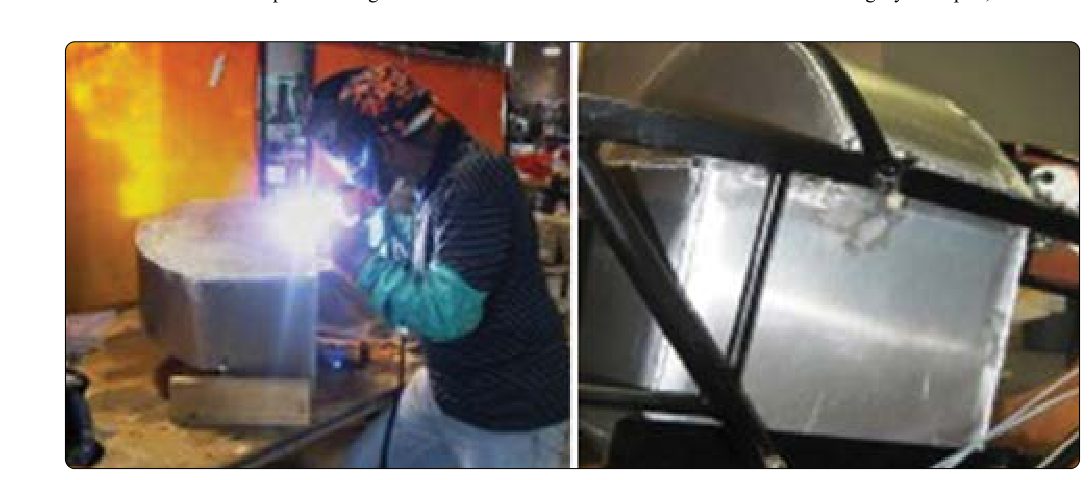
Repair of rigid tanks most commonly involves welding or patching cracks and pinholes in the aluminum skin. Welding of aluminum fuel tanks must be performed by a certificated welder using approved procedures, and the tank must be properly purged of fuel vapor before any heat is applied—fuel vapor ignition during welding is an ever-present hazard. After repair, the tank is pressure- or leak-tested to verify integrity before reinstallation.
Why Tank Type Matters for Maintenance
Knowing which type of tank an aircraft has directly determines the inspection approach, the approved repair methods, and the required materials. Using the wrong sealant in an integral tank, installing a bladder with kinked fittings, or failing to cushion a rigid tank's mounts are all errors that can lead to fuel leaks, engine power loss, or fire. The FAA makes these distinctions explicit in FAA-H-8083-31, and the aircraft's manufacturer maintenance manual (MM) is always the authoritative source for type-specific procedures and approved materials. No repair or modification to a fuel tank may use materials or methods not approved for that installation.
Key Numbers and Rules
- Fuel tank venting: All fuel tanks must be vented to prevent vacuum buildup during fuel flow or thermal contraction; vent lines must be positioned to prevent blockage by ice or water.
- Unusable fuel: The unusable fuel quantity (fuel that cannot be delivered to the engine under any normal flight attitude) must be established by test and placarded in the aircraft.
- Fuel cell replacement life: Many bladder cells carry a manufacturer-specified replacement interval regardless of apparent condition—always check the aircraft's maintenance manual and the cell manufacturer's data.
- Sealant cure time: Two-part polysulfide sealants used in integral tanks typically require a specific cure period (often 72 hours or more at specified temperature and humidity) before the tank is placed in service—verify with the approved data.
- Pressure testing: After repair or reassembly, tanks are typically leak-tested; the specific test pressure and duration are specified in the manufacturer's maintenance manual and must not be exceeded to avoid damaging tank structure.
- 14 CFR Part 43: All fuel tank repairs and alterations must be performed and documented in accordance with Part 43 using approved data; major alterations require FAA approval via Form 337 or Supplemental Type Certificate.
Common Test Traps
- Integral vs. bladder confusion: A wet wing is an integral tank—the structure IS the tank. A bladder cell is a separate flexible envelope inserted into a structural cavity. Do not confuse the two on the written or oral exam.
- Bladder collapse cause: Engine fuel starvation from a bladder tank does not always mean the tank is empty—a blocked vent can collapse the bladder and block the outlet while fuel remains in the cell. This is a favorite AMT exam scenario.
- Rigid tank cushioning: Chafing damage to rigid tanks is caused by inadequate or deteriorated cushioning between the tank and its mounts—not by the tank being too full. Always inspect cushion condition during annual or 100-hour inspections.
- Sealant is not just for leaks: Polysulfide sealant in an integral tank also serves as a corrosion barrier and must meet the manufacturer's specification for fuel compatibility and flexibility—generic household sealants are never acceptable.
- Unusable fuel is not zero: The FAA requires that unusable fuel be determined by test and properly accounted for in weight-and-balance documentation. Confusing usable and total capacity is a common computational error on knowledge tests.