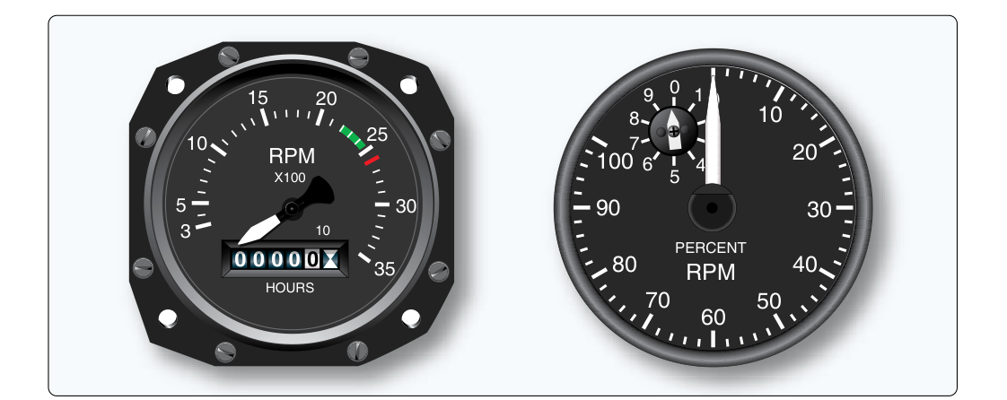
In any gas turbine engine — whether a turbofan, turbojet, turboprop, or turboshaft — the rotating spools are the heart of the powerplant. Knowing how fast those spools are turning is not a luxury; it is an operational necessity. The N1 and N2 tachometer generator systems are the instruments responsible for measuring and displaying those rotational speeds. Understanding how these systems work, how they are calibrated, and why accurate readings matter is fundamental knowledge for any Aviation Maintenance Technician (AMT) working on turbine-powered aircraft.
Unlike reciprocating engine tachometers, which typically count crankshaft revolutions directly, gas turbine tachometer systems must measure the speed of multiple independent rotating assemblies spinning at very high RPM — sometimes well above 10,000 RPM for high-pressure spools. To handle these demands, turbine engines use electrical tachometer generator systems that convert mechanical rotation into an electrical signal and transmit that signal to a cockpit indicator or digital processing unit.
What N1 and N2 Mean
The letter N in gas turbine terminology simply denotes rotational speed of a spool. In a dual-spool engine — the most common configuration in modern commercial and military turbofans — there are two mechanically independent rotating assemblies:
- N1 (Low-Pressure Spool): This spool consists of the low-pressure compressor (fan in a turbofan engine) and the low-pressure turbine, connected by a common shaft. N1 speed is typically expressed as a percentage of a rated maximum RPM. In large turbofan engines, the fan is the primary thrust producer, so N1 is extremely important for thrust management.
- N2 (High-Pressure Spool): This spool includes the high-pressure compressor and the high-pressure turbine, connected by a separate, concentric shaft. The N2 spool spins faster than N1. In most turbofan engines, N2 also drives engine accessories through the accessory gearbox. N2 speed is also expressed as a percentage of rated maximum RPM.
Some engines — particularly large three-spool turbofans used on certain wide-body aircraft — also have an N3 (Intermediate Spool) with its own tachometer system, but the N1/N2 dual-spool arrangement covers the vast majority of turbine engines an AMT will encounter.
How the Tachometer Generator System Works
The tachometer generator — sometimes called a tacho-generator or simply a tach-gen — is an AC generator driven directly by the engine spool it is measuring. The N2 tach-gen is typically mounted on the engine accessory gearbox, while the N1 tach-gen drive arrangement varies by engine design — some are driven from the front (fan) section, others through a shaft or gear train specific to that engine model. The fundamental operating principle is electromagnetic induction: as the rotor of the tachometer generator spins, it induces an alternating current (AC) in the stator windings. The frequency of this AC output is directly proportional to the rotational speed of the spool driving it. The voltage amplitude also varies with speed, but it is the frequency — not the voltage — that the indicating system uses to determine RPM.
The AC signal is transmitted through shielded wiring to the cockpit indicator. In older, simpler systems, a synchronous motor in the indicator receives the AC signal, its rotor locks onto the frequency, and a mechanical linkage drives the pointer. Because the indicator motor synchronizes exactly with the generator frequency, the pointer position is a direct, real-time representation of engine spool speed. These are sometimes called AC synchro tachometer systems.
In modern aircraft with digital avionics suites — such as FADEC-equipped engines and EFIS-based displays — the tachometer generator signal is fed to an engine monitoring computer or Full Authority Digital Engine Control (FADEC) unit. The computer measures the signal frequency with high precision, converts it to an RPM value, and sends a digital data word to the cockpit display system. The pilot sees the result as an N1 or N2 percentage readout on an Engine Indicating and Crew Alerting System (EICAS) or Electronic Centralized Aircraft Monitor (ECAM) display.
Percentage vs. Actual RPM
Turbine engine spool speeds are almost universally displayed as a percentage of a rated maximum RPM rather than in actual RPM. This is done for standardization and operational simplicity. For example, if a given high-pressure compressor spool has a rated maximum RPM defined as 100% for that engine, an N2 reading of 95% means the spool is turning at 95% of that specific engine's rated maximum — the actual RPM value corresponding to 100% varies by engine model and is established during certification. The rated maximum (100%) for each spool is defined during engine certification and is built into the tachometer generator gear ratio and/or the indicator's calibration. This means that operating limits, takeoff settings, and idle speed parameters are all described in percentage terms — a consistent, engine-family-independent language that applies whether the engine is new or overhauled.
Tachometer Generator Construction and Installation
A typical tachometer generator is a small, robust AC generator, built as either a single-phase or three-phase design depending on the manufacturer and application. Key construction features include:
- Permanent magnet rotor: Most tach-gens use a permanent magnet rotor, which means they require no external excitation power to generate an output signal. This makes them self-contained, reliable, and fail-safe in the sense that a loss of aircraft electrical power does not cause the tach-gen itself to stop generating a signal (though displays may lose power).
- Drive coupling: The tach-gen is driven through a flexible coupling or drive pad on the accessory gearbox, or, for some N1 installations, through a shaft or gear arrangement specific to the engine design. The gear ratio between the engine spool and the tach-gen shaft is precisely set so that the generator produces a specific output frequency when the spool reaches its rated maximum speed.
- Environmental sealing: Tachometer generators are typically sealed against moisture, oil, and contamination. They are qualified to operate across wide temperature ranges given their exposure to engine nacelle environments.
- Shielded wiring harnesses: The low-level AC signal transmitted from tach-gen to indicator is susceptible to electromagnetic interference (EMI). Shielded cables and proper grounding are essential to prevent erroneous speed indications caused by interference from ignition systems, generators, or avionics.
Why N1 and N2 Accuracy Matters
Accurate N1 and N2 readings are critical for multiple reasons that span flight operations, maintenance, and safety:
- Thrust management: Takeoff thrust settings are set by referencing N1 (in most turbofan operations). An inaccurate N1 reading can cause a crew to apply too little thrust for takeoff or to over-speed an engine, with potentially catastrophic consequences. The AMT must ensure tach-gen systems are properly calibrated and that indicator readings match actual spool speed.
- Engine operating limits: Both N1 and N2 have maximum continuous, takeoff, and transient limits established during engine certification and published in the Type Certificate Data Sheet (TCDS) and the Aircraft Flight Manual (AFM). Exceeding these limits can cause turbine blade overstress, compressor surge, bearing damage, or catastrophic structural failure. Accurate tachometer readings are the only way crews and engine control systems can enforce these limits.
- Idle speed verification: Ground idle and flight idle N1/N2 speeds are specified in the engine maintenance manual. Mechanics verify these during ground runs after maintenance. Incorrect idle settings affect fuel flow, bleed air availability, and deceleration characteristics.
- Trend monitoring and diagnostics: Over time, changes in N1 or N2 at a given fuel flow or throttle position can indicate compressor erosion, turbine degradation, or developing mechanical problems. Accurate tachometer systems make meaningful trend monitoring possible.
Key Numbers and Rules
- N1 and N2 are expressed as a percentage of rated maximum RPM, not in actual RPM on cockpit indicators.
- The tachometer generator output frequency — not voltage — is proportional to spool speed and is used by the indicating system.
- Most tach-gens use permanent magnet AC generator designs, either single-phase or three-phase, requiring no external excitation.
- The gear ratio between the engine spool and tach-gen is set so that 100% spool speed corresponds to a specific, calibrated output frequency.
- Shielded wiring is mandatory to prevent EMI from corrupting the low-level AC tachometer signal.
- On dual-spool turbofans, N2 typically spins faster than N1 and drives the accessory gearbox.
- FADEC systems use tachometer generator signals as primary inputs for engine control; erroneous N1/N2 signals can cause FADEC to mismanage fuel scheduling.
Troubleshooting and Maintenance Considerations
When an N1 or N2 indicator shows an erratic, stuck, or obviously incorrect reading, the AMT should follow a logical diagnostic sequence. First, determine whether the fault is in the tachometer generator itself, the wiring harness, or the cockpit indicator. Common failure modes include tach-gen bearing failure (produces erratic or frozen indication), broken or corroded wiring (can produce zero reading or noise), and indicator motor failure in older synchro-type systems. On aircraft with FADEC or digital engine management, the maintenance computer will typically log fault codes that identify whether the out-of-range signal originated at the generator or elsewhere in the data path. The aircraft manufacturer's maintenance manual and component maintenance manual (CMM) provide the specific resistance checks, frequency output specifications, and replacement criteria that govern tach-gen serviceability.
Common Test Traps
- Voltage vs. frequency: A common exam mistake is stating that the tachometer generator signal voltage is what indicates speed. The correct answer is frequency. Voltage changes too, but frequency is the measured parameter.
- RPM vs. percentage: Students sometimes expect N1 and N2 to be displayed in actual RPM. On virtually all turbine aircraft, these are displayed as a percentage of rated maximum.
- N1 is not always the faster spool: N2 (high-pressure spool) rotates faster than N1 in most turbofan engines. Do not assume N1 means the fastest-spinning spool.
- External excitation: Because most tach-gens use permanent magnet rotors, they do NOT require external electrical excitation to generate a signal — unlike aircraft alternators that need field current. This is a frequently tested distinction.
- Shielding importance: Failing to appreciate that tachometer wiring must be shielded against EMI is a common oversight. Unshielded wiring in this application would allow interference to corrupt speed readings, a direct safety concern.