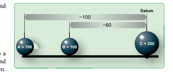
Every aircraft in service has an invisible vertical reference plane built into its design — a line from which all weight and balance measurements flow. This plane is called the datum (sometimes written as the datum reference plane or reference datum), and understanding where it is located and why it matters is one of the most fundamental concepts in aircraft weight and balance. Whether you are computing a loading problem for a Cherokee, a King Air, or a transport-category freighter, every arm distance you use originates from this single imaginary line.
For AMT students preparing for the FAA General knowledge test, mastering the datum concept means more than memorizing a definition. You need to understand how manufacturers choose the datum location, how that choice affects the sign (positive or negative) of arm measurements, and how you apply this knowledge to calculate moments and center of gravity. This article walks through all of that in detail.
What the Datum Actually Is
The datum is described in the FAA Weight and Balance Handbook (FAA-H-8083-1) as an imaginary vertical plane from which all horizontal distances are measured for weight and balance purposes. The word "horizontal" is key: the datum is vertical in orientation, and the distances measured from it — called arms — run horizontally along the aircraft's longitudinal axis, forward and aft.
The datum has no physical existence on the aircraft. You cannot touch it or see it. Its reality lives entirely in the aircraft's Type Certificate Data Sheet (TCDS) and Weight and Balance Report. Once the manufacturer fixes its location, it stays fixed for the life of that aircraft type. It never moves relative to the airframe.
The arm of any item — a passenger seat, a fuel tank, a cargo pallet, an engine — is the horizontal distance in inches from the datum to that item's center of gravity. When you multiply an item's weight (in pounds) by its arm (in inches), you get its moment (in pound-inches). Sum all the weights to get total aircraft weight; sum all the moments; divide total moment by total weight to find the aircraft's center of gravity location. That CG location is expressed as an arm — the number of inches forward or aft of the datum.
How Manufacturers Choose the Datum Location
The FAA does not mandate a specific datum location. According to FAA-H-8083-1, the manufacturer may select any convenient point as the datum, provided it is used consistently throughout all weight and balance documentation for that aircraft model. This flexibility is intentional: different designs benefit from different reference points.
In practice, three common datum locations appear across the general aviation and transport fleets:
- The firewall or nose of the aircraft: Many single-engine piston aircraft place the datum at or near the firewall, or at the most forward point of the aircraft (the spinner or nose). When the datum is at or forward of the nose, all arms are positive numbers, which simplifies arithmetic and reduces sign errors.
- Some distance ahead of the nose: Many transport-category aircraft and some turboprops place the datum a fixed number of inches forward of a reference structure — for example, 100 inches ahead of the nose of the fuselage. Again, this ensures all useful arm measurements are positive.
- The leading edge of the mean aerodynamic chord (MAC): Some manufacturers, particularly for jets, anchor the datum to an aerodynamic reference. This ties weight and balance directly to aerodynamic behavior and makes CG expression as a percentage of MAC straightforward.
Regardless of placement, the overriding design goal is consistency and convenience. A datum far forward of the aircraft ensures that all stations are positive numbers, which reduces the chance of arithmetic errors during loading calculations. Some older designs do place the datum within or behind the aircraft structure, which creates negative arm values for stations forward of the datum. Both systems are legal, but the AMT must read the aircraft's TCDS carefully to know which applies.
Fuselage Stations and the Datum
The datum gives birth to the system of fuselage stations. Each station is simply a distance in inches from the datum, measured along the aircraft's longitudinal axis. A fuselage station labeled FS 137.5 means that point is 137.5 inches aft of the datum. When the datum is forward of the aircraft, all fuselage stations are positive. When the datum falls within the fuselage, stations aft of it are positive and stations forward of it are negative.
Manufacturers publish a station diagram or fuselage station chart in the aircraft's maintenance manual and weight and balance data. This chart identifies the station number for every significant item: seats, fuel tanks, baggage compartments, engines, avionics bays, and so on. The AMT uses these published station numbers as arm values directly in moment calculations — there is no need to re-measure anything physically if the documentation is available and accurate.
Locating the Datum in Practice
The authoritative source for datum location is the aircraft's Type Certificate Data Sheet (TCDS), published by the FAA and freely available on the FAA's TCDS database. The TCDS states the datum location explicitly. For example, a TCDS might read: "Datum: 78.4 inches forward of the leading edge of the wing at the root." That sentence is all you need to anchor every arm measurement for that aircraft type.
The aircraft's Weight and Balance Report — the document that accompanies the specific aircraft, not just the type — will also reference the datum and list each item's arm. When an aircraft is modified, an STC or field approval may add new equipment with newly calculated arm values, all referenced to the same original datum. The datum never changes between modifications; only new arm values are added to the documentation.
If you are working from the aircraft's Pilot's Operating Handbook or Airplane Flight Manual (AFM), the weight and balance section will state the datum location in its introduction and then list loading items and their arms. Always confirm you are reading from the correct document for that specific aircraft's serial number, because even minor production variations can affect published arms.
Why the Datum Location Matters for Safety
The datum is not a bureaucratic formality — it is the anchor of the entire CG calculation system. An error in identifying the correct datum, or confusion between positive and negative arms, can produce a calculated CG that is dangerously wrong. An aft CG reduces the aircraft's static longitudinal stability and can leave a dangerously small margin for stall recovery, making an inadvertent stall harder to recover from. A CG too far forward increases stall speed and can require more nose-up elevator authority than is available, which may prevent the pilot from flaring effectively during landing. In severe cases, either condition can be fatal.
For transport-category aircraft, the consequences scale with the number of passengers and the size of the aircraft. FAA-H-8083-1 emphasizes that CG must remain within the approved envelope for all phases of flight, and that envelope is defined relative to — you guessed it — the datum. Every structural limit, every aerodynamic certification, every performance chart assumes weight is distributed relative to the CG limits expressed in inches from that datum.
Key Numbers and Rules
- The datum is defined by the manufacturer, not the FAA, and is documented in the TCDS.
- Arms measured aft of the datum are positive (+); arms measured forward of the datum are negative (–). This is a fixed sign convention. If the manufacturer places the datum forward of every station on the aircraft, all stations will simply happen to be positive — because they are all aft of the datum — but the underlying rule does not change.
- The moment of any item equals its weight × arm (pounds × inches = pound-inches).
- CG location equals total moment ÷ total weight, expressed in inches from the datum.
- The datum location never changes when equipment is added, removed, or relocated — only the arm values and moments for individual items change.
- Always verify the datum in the aircraft's TCDS before performing any weight and balance calculation on an unfamiliar aircraft type.
Common Test Traps
- Assuming the datum is always at the nose: It is not. The TCDS defines the datum, and it may be ahead of, at, or behind the nose depending on the manufacturer's choice. Never assume — always check.
- Forgetting sign convention: If the datum falls inside the aircraft structure, items forward of it have negative arms. Using a negative arm as if it were positive — or vice versa — produces a completely wrong CG calculation. FAA knowledge test questions frequently test whether students handle negative arms correctly.
- Confusing the datum with the CG limits: The datum is a fixed reference plane. The forward and aft CG limits are separate values expressed in inches from the datum. The datum does not move; the CG does, depending on loading.
- Using arms from the wrong document: Arms are aircraft-specific. Using weight and balance data from the wrong serial number or an outdated manual is a real-world and test-question trap. Always use the document that matches the specific aircraft.
- Mixing units: All FAA weight and balance calculations use pounds for weight and inches for arm. Moments are pound-inches. Never mix feet and inches in the same calculation without converting first — a common arithmetic error on the knowledge test.