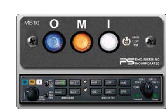
When you fly an ILS approach down to minimums in actual instrument meteorological conditions (IMC), two systems working together determine whether you land safely or execute a missed approach: the marker beacon system and your decision height (DH) discipline. Understanding how each marker beacon fits into the approach geometry — and exactly what must happen at decision height — is not just essential for the FAA Instrument Rating knowledge test; it could one day be the difference between a controlled landing and a controlled flight into terrain (CFIT) accident.
This article walks through every marker beacon type, the audio and visual cues each one provides, how they relate to the ILS glideslope and localizer, and the precise decision-height procedure that regulations and good airmanship demand.
ILS System Overview
The Instrument Landing System (ILS) is a precision approach system that provides both horizontal and vertical guidance to a runway. It consists of a localizer (lateral guidance), a glideslope (vertical guidance), and marker beacons (distance fixes along the final approach course). Some installations also include approach lighting systems (ALS) that extend beyond the runway threshold to help pilots transition visually at minimums. Together, these components define one of the most precise approach procedures in general aviation and airline operations.
How Marker Beacons Work
Marker beacons are ground-based VHF transmitters that radiate a narrow, fan-shaped signal vertically upward at a frequency of 75 MHz. The aircraft's marker beacon receiver — typically a dedicated receiver that shares an antenna with the interphone or audio panel — picks up the signal only when the aircraft flies directly through the fan. The signal is modulated with a specific audio tone and keying pattern that identifies which marker you are crossing. The cockpit indicator displays a colored light that flashes in synchronization with the audio.
Outer Marker (OM)
The outer marker is normally located approximately 4 to 7 nautical miles from the runway threshold, close to where the glideslope intercept altitude is reached on a procedure turn or feeder route. Its audio identification is a series of continuous dashes (— — —) transmitted at 400 Hz, and the cockpit light flashes blue. When you hear the low-pitched dashes and see the blue light, you are at the published glideslope intercept point. This is the cue to confirm gear down, final checklist complete, and approach clearance received. If an outer marker is not installed, a compass locator (LOM) — a low-frequency NDB co-located with the OM — or a DME fix may be substituted.
Middle Marker (MM)
The middle marker is positioned approximately 3,500 feet from the runway threshold, which typically corresponds to the vicinity of the ILS decision height on a standard 3° glideslope. Its audio is an alternating series of dots and dashes (· — · —) at 1,300 Hz — a medium-pitched, alerting tone — and the cockpit light flashes amber (yellow). Crossing the middle marker is a critical alerting cue: you are very close to DH, and if you have not already begun transitioning your scan for visual references, you must do so immediately. The middle marker also marks the point at which Category I ILS approaches reach decision height for many runway configurations.
Inner Marker (IM)
The inner marker, where installed, is located between the middle marker and the runway threshold. It is associated with Category II and Category III ILS approaches, where decision heights are lower and the need for precise positional awareness is even more acute. Its audio tone is continuous dots (· · · · · ·) at 3,000 Hz — a high-pitched rapid beeping — and the cockpit light flashes white. Inner markers are relatively rare and are only found at airports with Cat II/III certification.
Back Course Marker
Some ILS installations include a back course marker on the opposite end of the localizer course. It also displays a white light and uses a dot pattern similar to the inner marker, but it is positioned at the final approach fix for a back course localizer approach rather than near the runway. Pilots must not confuse a back course marker with an inner marker.
The Glideslope Relationship
Understanding where each marker falls on the glideslope helps you anticipate altitude. On a standard 3° glideslope, a rule of thumb is approximately 300 feet of altitude loss per nautical mile. At the outer marker (roughly 5 NM out), you might be intercepting the glideslope at around 1,500 feet AGL. By the time you cross the middle marker (~3,500 feet from the threshold), a standard Category I approach brings you to approximately 200 feet HAT (height above touchdown), which is why the middle marker and Cat I decision height align so well. Actual published minimums vary by airport and procedure — always verify against the specific approach chart.
Decision Height: The Critical Moment
Decision height (DH) is defined in 14 CFR Part 1 as a specified height above the highest runway elevation in the touchdown zone at which a missed approach must be initiated if the required visual references have not been established. For ILS approaches, DH is expressed in height above touchdown (HAT), and the standard Cat I DH is 200 feet HAT with a minimum visibility of ½ statute mile or RVR 2,400 feet (RVR 1,800 feet at some facilities with specific approach lighting).
The key word in the definition is "initiated." The missed approach must begin at DH — not below it. You do not descend through DH and then look around. The moment your altimeter reads DH, you must have the required visual references or begin the missed approach immediately. This is a hard regulatory floor for precision approaches, unlike the minimum descent altitude (MDA) used on non-precision approaches, which functions more like a floor you may fly along.
Required Visual References at DH
Per 14 CFR 91.175, a pilot may not continue an approach below DH unless the aircraft is continuously in a position from which a normal landing can be made using normal maneuvers, and at least one of the following visual references for the intended runway is distinctly visible and identifiable: the approach light system (ALS), threshold, threshold markings, threshold lights, runway end identifier lights (REIL), visual approach slope indicator (VASI), touchdown zone or touchdown zone markings, touchdown zone lights, runway or runway markings, or runway lights. Spotting approach lights alone is generally sufficient to descend to 100 feet above the touchdown zone elevation — but you cannot land unless you also identify runway-specific elements (threshold, markings, or lights).
Why Marker Beacons and DH Matter
CFIT accidents during instrument approaches almost always involve one of two failures: the crew descends below minimums without adequate visual reference, or they lose positional awareness on the approach. Marker beacons address the second failure by giving redundant, unmistakable cues that you are at a specific point in space. A pilot who is heads-down troubleshooting an avionics issue when the amber light flashes and the medium-pitched dashes and dots sound has an immediate, automatic prompt: look up, you are near DH. This is why experienced instrument pilots set the marker beacon receiver audio to a comfortable but clearly audible level and brief the expected indications before every ILS approach.
Key Numbers and Rules
- Marker beacon frequency: 75 MHz (all markers share the same frequency; tone and light color differentiate them).
- Outer marker: ~4–7 NM from threshold; blue light; 400 Hz continuous dashes.
- Middle marker: ~3,500 ft from threshold; amber light; 1,300 Hz alternating dots and dashes.
- Inner marker: Between MM and threshold (Cat II/III only); white light; 3,000 Hz continuous dots.
- Cat I ILS minimums: 200 ft DH HAT; ½ SM visibility (or RVR 2,400 ft, sometimes 1,800 ft).
- Decision height vs. MDA: DH (precision) = hard limit, initiate missed approach AT DH; MDA (non-precision) = floor, do not descend below.
- Sensitivity: Some receivers have HIGH/LOW sensitivity settings; HIGH is used at low altitudes (below 1,000 ft AGL) to improve reliability of marker reception.
- Substitution: A compass locator (LOM/LMM) or a GPS/DME fix may be published as a substitute when a physical marker beacon is out of service.
Memory Aid
A classic way to remember the three markers in order is the phrase "Blue Amber White" — working from the farthest to the closest marker beacon to the runway: Blue = Outer (farthest), Amber = Middle (alert!), White = Inner (Cat II/III, closest). Some instructors pair this with the rhythm of the tones: dashes are slow and low (outer/blue), dots-and-dashes are medium (middle/amber), rapid dots are fast and high-pitched (inner/white) — the pitch and speed of the tone increases as you get closer to the runway.
Common Test Traps
- Confusing DH with MDA: DH is for precision approaches (ILS, PAR); MDA is for non-precision (VOR, NDB, LNAV). The FAA knowledge test frequently asks which type of approach uses which term — never mix them up.
- Outer marker color: Many students guess "white" for the outer marker because it is the first one encountered. The outer marker is blue. White belongs to the inner marker and back course marker.
- "At" DH, not "below" DH: Questions often offer answer choices that suggest it is permissible to go slightly below DH before deciding. The regulation says the missed approach must be initiated at DH.
- Approach lights allow descent to 100 ft, not to landing: Seeing only the approach lighting system authorizes you to descend to 100 feet above the touchdown zone elevation — you still need additional runway environment cues to complete the landing.
- Marker beacon frequency: All markers operate on 75 MHz. Questions sometimes imply each marker has a different frequency — they do not. The differentiation is entirely by audio tone modulation and indicator light color.