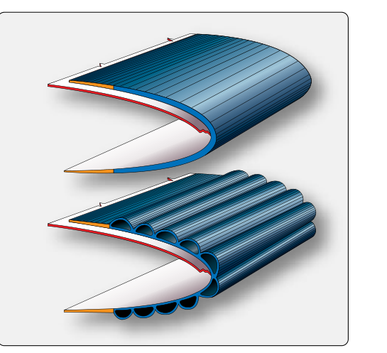
Pneumatic deicing boots are inflatable rubber bladder systems bonded to the leading edges of wings, horizontal stabilizers, and vertical stabilizers on many turboprop and some piston-powered aircraft. When ice accumulates, the boots inflate rapidly — typically with engine bleed air or a dedicated pneumatic pump — to mechanically crack and shed the ice buildup. Unlike anti-icing systems that prevent ice formation, deicing boots are designed to allow a modest layer of ice to form and then break it away, relying on aerodynamic forces to carry the debris clear of the airframe. Because these boots are primary components of a certificated icing protection system, their condition is directly tied to airworthiness, and their inspection, repair, and replacement fall squarely within the AMT's responsibility under 14 CFR Part 43.
This article walks through the complete maintenance cycle: how the system works, what to look for during inspection, how to address damage in the field, and when a boot must come off and be replaced entirely. Every step is grounded in the manufacturer's Structural Repair Manual (SRM), the applicable Instructions for Continued Airworthiness (ICA), and guidance found in the FAA's Aviation Maintenance Technician Handbook — Airframe (FAA-H-8083-31).
How Pneumatic Deicing Boots Work
A deicing boot assembly consists of an outer layer of neoprene or synthetic rubber, an internal network of spanwise and chordwise inflation tubes, and an inner ply that bonds directly to the leading edge skin. When the pilot activates the system, a pneumatic distributor valve cycles pressurized air — the exact pressure is aircraft-specific and must be verified against the applicable AFM/SRM data — into alternating tube sections. The tubes expand outward, deforming the boot surface and shattering the ice shell that has formed over them. After a brief inflation cycle, the tubes are deflated and the boot returns to its streamlined shape, ready for the next cycle.
On many turboprop aircraft, engine bleed air is routed through a pressure regulator and a distributor or timer valve to the boots. On some piston aircraft or retrofit installations, an engine-driven pneumatic pump supplies the pressure. A vacuum (suction) source is often used to hold the deflated boot tightly against the leading edge between cycles, preventing flutter and aerodynamic distortion. Cycle timing between inflations is aircraft- and system-specific — some systems are pilot-selectable or timer-controlled — and should be verified against the manufacturer's AFM/SRM data rather than treated as a fixed interval.
The bond between the boot and the leading edge skin is critical. Most boots are bonded with a contact-type cement during original installation, with the leading edge surface carefully prepared to ensure adhesion. Any loss of bond — even in a small area — can allow air to enter, causing the boot to balloon unevenly, reducing ice-shedding effectiveness, and potentially creating an aerodynamic penalty.
Inspection Procedures
Deicing boot inspections occur at multiple levels: preflight walkaround checks performed by the crew, periodic maintenance inspections in accordance with the aircraft's approved maintenance program, and special inspections after specific events such as bird strikes, hail, or ground damage. As an AMT, you are primarily responsible for the maintenance and periodic levels.
Visual Inspection
Begin every inspection with a thorough visual scan of the entire boot surface in good lighting. Work systematically from one end of the leading edge to the other. Look for the following discrepancies:
- Surface cuts and abrasion: Small cuts, nicks, and abrasions are common from gravel, sand, and debris. Even shallow cuts must be measured; if they penetrate through the outer ply into the tube structure, the boot is no longer airworthy without repair.
- Delamination and debonding: Press lightly along the chordwise and spanwise edges of the boot. A properly bonded boot will feel solid. A hollow or springy feel, a visible gap, or a bubbled surface indicates debonding from the leading edge skin. Small debonded areas may be repairable; large or structurally significant areas typically require replacement.
- Ozone and weather cracking: Neoprene rubber degrades with age and ozone exposure, producing a network of fine surface cracks. Light surface crazing that does not penetrate the outer ply may be acceptable per the SRM, but deep cracking that reaches the reinforcing fabric layer is cause for replacement.
- Erosion: The leading edge of the boot — the very tip of the inflation tube area — is most vulnerable to rain and sand erosion. Many installations include an erosion shield (a polyurethane or metal tape) at the leading edge. Inspect this shield for wear-through or lifting edges.
- Punctures and holes: Any through-hole in the boot wall is a maintenance item requiring immediate attention, as it will cause the system to bleed down pressure and fail to fully inflate.
- Cement condition: Look at the bond line where the boot meets the aircraft skin. Cracked or dried-out cement that has pulled away from the edge requires resealing.
Operational (Inflation) Check
With the aircraft properly powered and pneumatic system active, cycle the deicing boots while an assistant observes from outside. Each boot section should inflate visibly and uniformly within the manufacturer's specified time — inflation duration is aircraft-specific and should be checked against the SRM rather than assumed — and return to a flat, streamlined profile upon deflation. Uneven inflation, slow inflation, or failure of any section to fully deflate points to leaks, valve problems, or tube damage. Use a calibrated pressure gauge at the service port if the SRM calls for pressure verification. Listen for audible leaks during inflation, which can help localize a tube perforation.
Repair Procedures
Minor field repairs to deicing boots are permitted provided they fall within the limits spelled out in the aircraft SRM and the boot manufacturer's repair manual (companies such as Goodrich/Collins Aerospace and Dunlop publish their own repair data). All repairs must be documented in the aircraft maintenance records per 14 CFR Part 43.9.
Surface Cuts and Small Punctures
Clean the damaged area with an approved solvent to remove all contamination. Abrade the surface lightly with fine-grit sandpaper to improve adhesion. Apply a patch of compatible neoprene material, sized according to the overlap dimensions specified in the applicable SRM or boot manufacturer's repair manual, using two coats of the manufacturer-specified boot cement. Allow each coat to reach the proper tack before mating the surfaces. Roll out air bubbles, and allow the patch to cure fully according to the adhesive manufacturer's instructions. Verify that the patch is not located in an area where the SRM prohibits repairs (e.g., on the leading edge of the tube itself or within a critical inflation zone).
Debonding Repair
If the boot has lifted from the leading edge skin in a limited area, the repair involves carefully working boot cement under the debonded section using a thin spatula or syringe, re-pressing the boot to the skin, and clamping or taping it during cure. The adhesive used must be compatible with both the boot material and the aircraft skin (aluminum, composite, or other). After cure, run a bond check by pressing along the repaired area; it should feel solid. Large debonded areas — or debonding that extends across a tube section — generally exceed field repair limits and require boot replacement.
Boot Replacement
When a boot has damage beyond repair limits, has reached its service life limit (if defined by the manufacturer), shows widespread ozone cracking, or has a delaminated area too large to repair, it must be replaced. Boot replacement is a significant maintenance task that must be accomplished in accordance with the SRM and typically requires an airframe-rated AMT or a repair station with appropriate capability.
The replacement process begins with removing the old boot by carefully cutting the edge sealant and peeling the boot from the leading edge skin. All residual adhesive must be removed — usually with an approved solvent and careful mechanical scraping — without gouging or scoring the leading edge skin. The skin must be inspected for corrosion, scratches, or damage before the new boot is installed.
New boot installation requires applying primer and adhesive to both the skin and the new boot's inner surface, precisely aligning the boot (especially the tube array relative to the leading edge), rolling it down to eliminate air pockets, and allowing full adhesive cure under the conditions specified in the SRM. Edge sealant is then applied to all perimeter seams. After installation, a full operational check — including inflation timing, pressure hold, and visual observation — confirms airworthiness before the aircraft is returned to service.
Why It Matters
A deicing boot that cannot fully inflate or that debonds in flight provides false protection. A crew who activates the boots expecting ice to shed may continue flying into icing conditions with no actual protection — a situation that has contributed to fatal accidents. The FAA emphasizes that the airworthiness of ice protection systems is not optional equipment management. Restrictions on flight into known icing with an inoperative or degraded ice protection system are generally derived from compliance with the aircraft's AFM operating limitations and equipment list under 14 CFR 91.9, and, for aircraft with an approved MEL, from the applicable MEL provisions under 14 CFR 91.213 (or the equivalent Part 135 MEL) rather than a single standalone Part 91 rule.
Key Numbers and Rules
- Inflation pressure: Aircraft-specific; always verify with the AFM/SRM rather than assuming a standard range.
- Patch overlap dimensions: Specified by the boot/aircraft manufacturer's SRM or repair manual — not a standardized figure.
- Patch cure time: Per the adhesive manufacturer's instructions; varies by product.
- Regulatory authority: 14 CFR Part 43 governs all maintenance, alteration, and recordkeeping.
- Data source hierarchy: Aircraft SRM → Boot manufacturer's repair manual → FAA-H-8083-31 general guidance.
- Return to service: Operational inflation check required after any repair or replacement before flight.
Common Test Traps
- Deicing vs. anti-icing confusion: Pneumatic boots are a deicing system — they remove ice after it forms. Anti-icing systems (heated leading edges, TKS fluid) prevent formation. Confusing the two on an exam is a common error.
- Repair limits exist: Not all boot damage is field-repairable. The SRM defines maximum damage limits; exceeding them requires replacement, not a larger patch.
- Adhesive compatibility: Using the wrong cement type — even one that bonds — can cause premature delamination or damage the boot material. Always use manufacturer-specified materials.
- Vacuum hold-down is part of the system: Many tests probe whether candidates know that the vacuum source keeps the boot flat during the deflated phase. Ignoring this during troubleshooting leads to misdiagnosis of flutter or billowing problems.
- Recordkeeping is mandatory: Any repair or replacement must be logged with a description of work, parts used, and the AMT's signature and certificate number per 14 CFR 43.9 — forgetting this step is both a regulatory violation and a test answer.