Ice accumulation on a rotating propeller is one of the most hazardous and underappreciated threats in cold-weather flight operations. Even a thin, rough layer of ice on a propeller blade dramatically alters its airfoil cross-section, degrading thrust, increasing drag, and inducing dangerous vibration as ice sheds unevenly from the blades. Beyond performance loss, chunks of shed ice can strike the fuselage, engine cowling, or even penetrate the cabin. For these reasons, aircraft certified for flight into known icing conditions must be equipped with propeller protection systems that either prevent ice from bonding in the first place — anti-icing — or periodically break off accumulated ice — de-icing. This article covers both types, how they work mechanically and electrically, how technicians maintain them, and why every AMT working on turboprop or piston twin powerplants must understand them thoroughly.
Anti-Icing vs. De-Icing: The Critical Distinction
The terms are often used loosely, but they describe fundamentally different strategies. An anti-icing system operates continuously whenever icing conditions exist, keeping the blade surface warm enough so that supercooled water droplets striking it cannot freeze — they simply run off. A de-icing system is cyclic: it allows a thin layer of ice to form, then applies heat or another force to break the bond between ice and blade, allowing centrifugal force to sling the loosened ice away. Each approach has trade-offs in power consumption, system complexity, and effectiveness at various temperatures and airspeeds, and understanding those trade-offs is essential background for the AMT knowledge test.
Fluid Anti-Icing Systems (Isopropyl Alcohol)
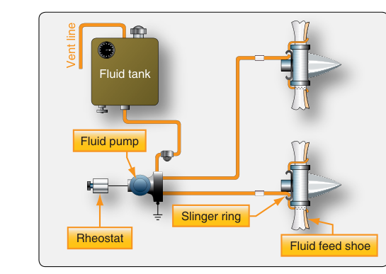
The earliest and simplest propeller protection method uses a pump to distribute isopropyl alcohol (or a purpose-formulated glycol-alcohol blend) from a reservoir through slinger rings mounted on the propeller hub. The slinger ring contains small ports aligned with feed tubes that run along the leading edge of each blade. As the propeller spins, centrifugal force moves the fluid outward along these tubes, coating the blade leading edge with a thin film. Because alcohol lowers the freezing point of water, the fluid film on the blade resists freezing, preventing ice from forming in the first place rather than removing ice that has already bonded.
Key maintenance considerations for fluid systems include: checking reservoir fluid levels, inspecting slinger ring ports for blockage, verifying feed tube integrity, and confirming proper pump output pressure. The system is effective but has limitations — it consumes fluid quickly and may be inadequate in severe or prolonged icing conditions. Fluid anti-icing is most common on light piston aircraft and older designs. The pilot controls flow rate via a rheostat or selector switch, and the AMT must verify that the correct approved fluid type is used and that reservoir capacity meets the aircraft's approved flight manual requirements.
Electrical De-Icing Systems
By far the most common system on modern turboprops and multi-engine piston aircraft, electrical propeller de-icing uses resistance heating elements embedded in neoprene rubber boots bonded to the leading edges of the propeller blades. When current flows through these elements, the resistance of the wire generates heat (Joule heating), warming the boot surface and breaking the adhesive bond between ice and blade. Centrifugal force then slings the loosened chunks outward and away.
System Architecture
Because applying power to all blades simultaneously would draw enormous current and leave all blades simultaneously vulnerable between cycles, electrical de-icing systems use a timer — typically called a de-ice timer or cycling timer — to sequence power to individual blades or groups of blades in rotation. A typical installation might heat the inboard section of each blade for a set interval, then the outboard section, cycling through all blades before repeating the sequence. Exact cycle timing varies by aircraft model, manufacturer, and icing severity, and must be verified in the applicable aircraft maintenance manual rather than assumed from a general rule.
Current is delivered from the aircraft's electrical bus through a slip ring assembly on the rear face of the propeller hub — or on the engine nose case behind it. Carbon brushes press against the slip rings, maintaining contact as the propeller rotates. Each blade element connects via leads that pass through the hub to the appropriate slip ring segment. This brush-and-ring interface is one of the most common maintenance trouble spots: brushes wear, slip ring surfaces develop grooves or oxidation, and brush spring tension weakens over time, all of which cause intermittent heating or complete element failure.
Heating Element Construction
The heating elements themselves are fabricated from a resistance wire or metallic foil encapsulated between layers of fiberglass-reinforced rubber. The completed assembly is bonded to the blade leading edge using approved adhesives, then vulcanized or cured. Each element has a precisely calculated resistance, which the AMT can measure with an ohmmeter to confirm serviceability. Manufacturer specifications list acceptable resistance ranges for each blade element; a reading outside that range indicates a break in the element or deterioration of the insulation. Most manufacturers also specify maximum allowable element-to-blade electrical leakage (insulation resistance), measured with a megohmmeter.
System Controls and Cockpit Integration
From the cockpit, the pilot activates propeller de-icing with a dedicated switch, often labeled PROP DE-ICE, which energizes the timer circuit. An ammeter or load meter is usually provided so the crew can confirm that current is flowing to the elements during each cycle phase — no current on a blade's cycle phase indicates a failed element or brush problem. Some aircraft include a separate PROP DE-ICE AMPS indicator. The AMT must verify during ground checks that ammeter deflection matches expected current draw for each cycling phase; a significantly lower-than-expected reading typically points to a broken element, while a higher reading may indicate a short circuit.
Maintenance Inspections and Common Defects
FAA guidance and manufacturers' maintenance manuals require periodic inspection of all propeller de-icing components. Standard inspection tasks include:
- Visual inspection of boots: Look for cuts, cracks, disbonding at leading edge, erosion wear-through that exposes heating elements, and delamination. Minor surface erosion may be acceptable within limits, but any breach of the element is cause for replacement.
- Resistance check of each element: Performed with a calibrated ohmmeter. Compare measured resistance to the manufacturer's specified range. Perform the check at a known ambient temperature, as resistance varies with temperature.
- Insulation resistance check: Use a megohmmeter (megger) at the voltage specified by the manufacturer's maintenance manual for that specific element and aircraft. Confirms insulation integrity between the heating element and the metallic blade structure. A low reading indicates deteriorated insulation that could cause current leakage or a short to ground.
- Slip ring and brush inspection: Measure brush length against the minimum serviceable limit. Inspect slip ring surface for grooving, pitting, or corrosion. Check brush spring tension with a spring scale if required. Clean oxidized slip ring surfaces with approved methods — never use abrasives that could introduce conductive contamination.
- Timer and cycling verification: Using an ammeter, confirm that the timer sequences power correctly to each blade or element group in the prescribed order and interval. A sticking or failed timer can leave some blades permanently heated (fire or burn-through risk) or unheated (ice accumulation).
- Wiring and connector inspection: Inspect hub wiring for chafing against rotating components, particularly where leads exit the hub. Verify connector pins are clean, tight, and corrosion-free.
Why Propeller Ice Protection Matters
Ice accumulation on propeller blades reduces efficiency by disrupting the blade's carefully designed airfoil shape — the same reason airframe icing is so dangerous. The increase in drag and decrease in thrust can be significant even with modest accumulation. More immediately alarming is the asymmetric shedding problem: if one blade sheds ice before another, the mass imbalance creates severe propeller vibration that can damage engine mounts, crack the airframe, and even cause propeller failure. The cyclic timing design of electrical de-ice systems mitigates this by heating blades in a balanced sequence, ideally causing balanced shedding.
On multi-engine aircraft with wing de-ice boots, the propeller system is an equally critical part of the overall ice protection package. An aircraft certificated for flight into known icing conditions (FIKI) must have all required anti-/de-icing systems fully functional before departure into icing. A failed propeller de-ice element discovered during preflight is a go/no-go maintenance item, not a deferral to be taken lightly.
Key Numbers and Rules
- Electrical element resistance must be within the manufacturer's specified range — check with an ohmmeter at a known temperature.
- Insulation resistance is checked with a megohmmeter at the voltage and minimum acceptable value specified in the applicable maintenance manual, which varies by aircraft and element design.
- Brush wear limit is manufacturer-specific; always compare measured length to the minimum length in the manual before returning to service.
- De-icing cycle timing is aircraft-specific and must be verified in the applicable maintenance manual — there is no single FAA-mandated cycle time to memorize.
- Fluid anti-icing systems use isopropyl alcohol or an approved glycol-alcohol blend — never substitute unapproved fluids.
- All repairs or replacements on propeller de-ice boots must follow 14 CFR Part 43 and the applicable manufacturer's maintenance manual or supplemental type certificate data.
Common Test Traps
- Anti-icing vs. de-icing confusion: Anti-icing is continuous and preventive; de-icing is cyclic and reactive. The FAA test frequently asks which term applies to fluid slinger systems (anti-icing) versus electrical boot systems (de-icing).
- Ohmmeter vs. megohmmeter: Element resistance is checked with a standard ohmmeter; insulation resistance is checked with a megohmmeter. Mixing these up on the test — or in the hangar — produces meaningless results.
- Slip ring brushes: A worn or sticking brush is a primary cause of intermittent de-icing; many questions probe whether the technician knows to check brush length, spring tension, and slip ring surface condition together.
- Asymmetric shedding hazard: Students sometimes think that running more heat continuously is better. The test may ask why continuous heating of all blades simultaneously is not done — the answer is excessive electrical load AND the risk of asymmetric shedding if one blade's element fails.
- Fluid type substitution: Only approved fluids may be used in fluid anti-icing systems. Using an unapproved substitute is an airworthiness violation regardless of how similar the fluid appears.