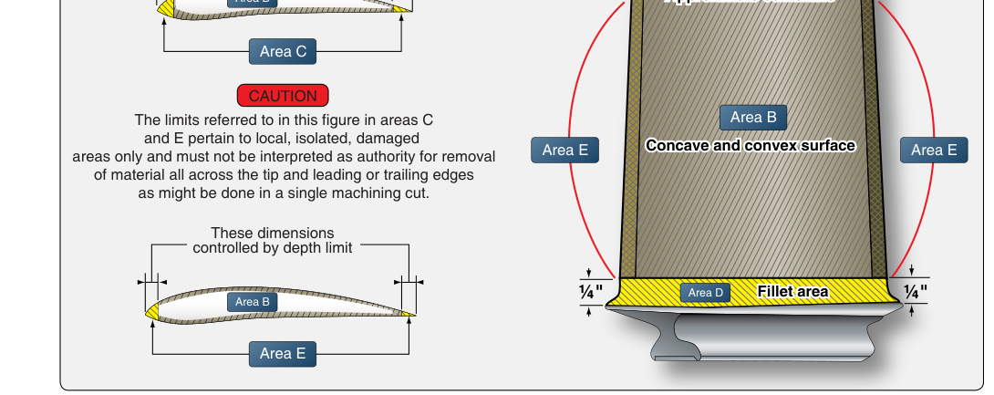
Propeller blades operate in a demanding environment — spinning at high RPM while absorbing engine torque, absorbing vibration, and enduring the constant impact of rain, dust, and debris. Even minor nicks, gouges, or corrosion can concentrate stress at the blade's leading edge or root, potentially leading to catastrophic fatigue failure. For this reason, the FAA and propeller manufacturers establish precise repair limits: boundaries that define the maximum allowable damage an AMT may correct in the field versus the damage that requires factory overhaul or blade replacement. Understanding these limits is essential for the AMT Powerplant certificate knowledge test and, more importantly, for keeping aircraft airworthy.
This article covers the regulatory framework for propeller blade repairs, the types of damage commonly found on metal and wood blades, the reconditioning procedures approved for each, and the inspection standards that govern return to service. All guidance is grounded in the FAA's Aviation Maintenance Handbook and the relevant provisions of 14 CFR Part 43 and Part 65.
Regulatory Foundation
The authority for propeller maintenance and repair flows from 14 CFR Part 43. Section 43.13 requires that maintenance be performed in accordance with the manufacturer's maintenance manual or Instructions for Continued Airworthiness (ICA), applicable FAA-approved data, or standard industry practices when no specific data exists. For propellers, manufacturers publish overhaul manuals that specify exact repair limits in measurable terms — allowable nick depth, chord reduction limits, and surface finish requirements. These documents are the first reference an AMT must consult before performing any blade repair.
Major repairs to propellers, including repairs that exceed published limits or restore a blade to original contour, are classified as major repairs under 14 CFR Part 43, Appendix A. A major repair may be performed by an appropriately certificated repair station, an FAA-certificated mechanic with the appropriate rating as authorized under 14 CFR 43.3, or the manufacturer. Holding an Inspection Authorization (IA) is not required to perform a major repair — IA relates to approving certain work for return to service (via FAA Form 337) and to annual/progressive inspections under 14 CFR 65.95, and for propellers that approval authority is generally reserved to a repair station or the manufacturer. Minor repairs — those within the manufacturer's published limits — may be performed by an AMT holding a Powerplant rating.
Types of Blade Damage
Nicks, Gouges, and Erosion
The most common blade damage is leading-edge nicks caused by gravel, sand, and runway debris. A nick creates a stress riser — a point where fatigue cracks can originate under the cyclic loading of each revolution. Shallow nicks on the leading edge of a metal blade are typically repensionable by filing and blending, provided the resulting material removal does not reduce blade chord or thickness beyond manufacturer limits. The repair must produce a smooth, rounded contour with no sharp edges or tool marks that could themselves become stress risers.
Trailing-edge gouges are generally more serious because the trailing edge is thinner and more prone to cracking. Many manufacturers prohibit any filing of the trailing edge and require blade replacement if damage extends below a specified depth. Erosion — the gradual wearing away of leading-edge material by rain and airborne particles — reduces blade efficiency and, over time, can thin the blade to below minimum thickness limits. Anti-erosion tape or coatings may be applied where approved by the manufacturer.
Corrosion
Aluminum alloy blades are susceptible to pitting corrosion, particularly near the blade shank where moisture can accumulate. Light surface corrosion may be removed by polishing with approved abrasive materials, followed by alodine treatment and application of a protective coating. However, intergranular corrosion — which attacks the metal below the surface — is cause for blade rejection. The distinction between superficial and intergranular corrosion requires careful inspection, and the AMT must be familiar with etching or dye penetrant methods used to reveal subsurface attack.
Cracks
Any crack in a propeller blade is grounds for immediate removal from service. Cracks are not repairable in the field. Dye penetrant inspection (DPI) and eddy current inspection are the standard non-destructive testing (NDT) methods used to detect surface and near-surface cracks. These techniques are particularly important at the blade root, where bending stresses are highest, and along any repair area where filing may have introduced tool marks. If a crack is found, the blade must be sent to a propeller repair station or replaced.
Specific Repair Procedures for Metal Blades
The standard reconditioning sequence for an aluminum propeller blade with minor leading-edge damage proceeds as follows:
- Damage assessment: Measure nick depth and width with a calibrated file gauge or micrometer. Compare to manufacturer limits. If the damage exceeds limits, stop — do not attempt repair.
- Filing: Use a smooth mill file to carefully remove the damaged material. File across the nick at an angle to avoid undercutting the blade surface. All strokes should flow into the blade contour.
- Blending: Blend the repaired area with fine-cut files and progressively finer abrasive cloth (emery or aluminum oxide) until the transition from the repair to the surrounding blade surface is smooth and gradual. The minimum blend ratio specified by most manufacturers is 10:1 — for every 0.010 inch of depth removed, the blend must extend at least 0.100 inch along the blade surface. Always verify the exact ratio in the manufacturer's manual.
- Chord measurement: After filing, measure the chord width at the repaired station and compare to the minimum chord limit in the overhaul manual. Cumulative repairs must not reduce chord below this limit.
- Surface finish inspection: Use a surface profilometer or tactile inspection to confirm that no tool marks or sharp transitions remain.
- NDT inspection: Perform dye penetrant inspection of the repair area to ensure no cracks were introduced during filing.
- Balancing check: Even a small amount of material removal changes blade mass. After any repair, static balance must be verified, and dynamic balance should be checked if the propeller is returned to service on a vibration-sensitive engine installation.
Wood Propeller Blade Repairs
Wood propellers, while less common on modern aircraft, are still found on many certificated and experimental aircraft. Damage types include leading-edge metal sheath separation, surface checks, splits, and moisture absorption. Minor surface checks and small nicks in the wood itself may be sanded smooth and refinished with approved varnish or epoxy. However, any split extending toward the hub, delamination of laminate plies, or separation of the leading-edge metal sheath beyond a small area is cause for rejection.
Wood blades must never be soaked in water or exposed to prolonged moisture, as swelling can distort the blade and alter pitch. After any reconditioning, the entire blade must be refinished to seal the wood against moisture penetration. Metal leading-edge sheaths that are loose must be re-bonded using manufacturer-approved adhesive; improper bonding can lead to sheath departure in flight, creating an extreme imbalance condition.
Propeller Balancing After Repair
Propeller balance is a safety-critical parameter. An out-of-balance propeller imposes cyclic loads on the engine crankshaft, propeller shaft bearings, and airframe — accelerating wear and potentially causing structural fatigue. Static balance is achieved when the propeller, placed on a horizontal arbor, remains stationary in any rotational position. Static imbalance is corrected by adding approved balance weights to the lighter blade or hub, or by removing small amounts of material from approved locations on the heavier side — always within manufacturer limits.
Dynamic balance, performed with a vibration analyzer while the engine is running, addresses imbalance forces that only appear during rotation. Dynamic balancing is increasingly required or recommended by manufacturers and is part of the return-to-service procedure after major blade repairs. The FAA's Aviation Maintenance Handbook (FAA-H-8083-32) provides detailed guidance on both balancing methods.
Key Numbers and Rules
- Blade chord reduction: Manufacturers typically allow no more than a specific percentage of original chord to be removed — commonly around 0.5% to 1% — but always reference the specific manual for exact limits.
- Blend ratio: Typically a minimum of 10:1 (length-to-depth) for leading-edge nick blending; verify with manufacturer data.
- Crack policy: Zero tolerance — any crack requires blade removal and referral to a rated repair station.
- Major repair classification: Repairs exceeding manufacturer limits are classified as major repairs under 14 CFR Part 43, Appendix A, and must be performed by an appropriately certificated repair station, an authorized mechanic, or the manufacturer.
- NDT after repair: Dye penetrant or eddy current inspection is required after any filing or grinding to confirm no cracks were introduced.
- Return to service: A completed repair must be documented in the aircraft maintenance records per 14 CFR 43.9, including the date, description of work, reference data used, and the AMT's certificate number and signature.
Common Test Traps
- Confusing minor and major repairs: A common test error is assuming any leading-edge nick repair is a minor repair. If the repair exceeds manufacturer limits — in depth, chord reduction, or area — it becomes a major repair requiring an appropriately certificated repair station, authorized mechanic, or the manufacturer.
- Forgetting the blend ratio requirement: Students often remember to file out a nick but forget that the blend transition must meet a minimum ratio. A sharp-edged repair is as dangerous as the original nick.
- Assuming a cracked blade can be repaired: No propeller blade crack is a field-repairable condition. This is an absolute: cracks mean rejection and overhaul-level repair.
- Neglecting balance after repair: Material removal changes blade mass. Skipping a balance check after any metal removal is an airworthiness violation and a common test question about return-to-service requirements.
- Failing to consult the manufacturer's manual first: The AMT must consult approved data — the manufacturer's ICA or overhaul manual — before any repair. Generic procedures are a starting point, not a substitute for model-specific limits.