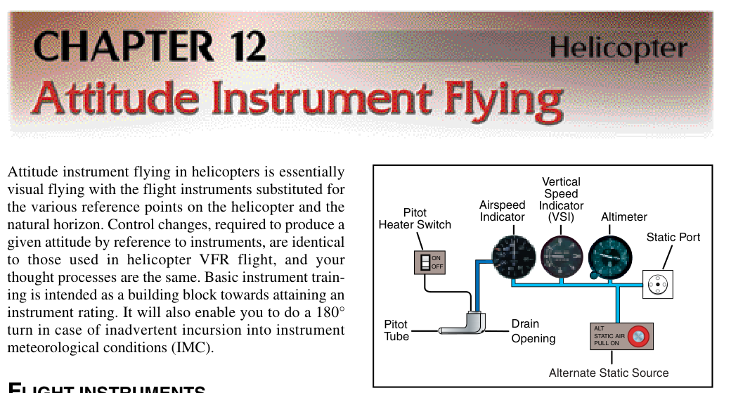
Among the most deceptively simple yet critically important systems on any aircraft are the pitot tube and static port heating elements. These small electrical heaters prevent ice from forming on — or inside — the openings that feed the aircraft's pitot-static system. When those openings become blocked by ice, the airspeed indicator, altimeter, and vertical speed indicator (VSI) all begin providing false information, sometimes with fatal consequences. Understanding exactly how pitot and static heat systems work, when they are required, and how to inspect and troubleshoot them is essential knowledge for every Aviation Maintenance Technician (AMT) working on airframe systems.
The pitot-static system operates on a straightforward pressure differential: the pitot tube senses ram (impact) air pressure, while one or more static ports sense ambient (undisturbed) atmospheric pressure. The instruments compare these pressures to display airspeed, altitude, and vertical speed. Any partial or complete blockage of either sensing point corrupts those pressure readings. Ice is an especially insidious blocking agent because it can accumulate in minutes during flight through visible moisture at or below freezing temperatures, and the pilot may have no immediate tactile or visual cue that a blockage is forming.
How Pitot and Static Heating Systems Work
Pitot heat systems use electrical resistance heating elements embedded within the pitot tube body itself. When electrical current flows through the resistive element — typically a nichrome or similar alloy wire wound around or cast into the tube — the element converts electrical energy to heat by the Joule effect. The tube body warms to a temperature well above freezing, preventing ice adhesion and evaporating any moisture that contacts the surface before it can accumulate.
Most general aviation pitot tubes operate on the aircraft's 28-volt DC or 14-volt DC bus, drawing anywhere from about 40 watts on a light single-engine aircraft to well over 100 watts on larger airframes. Larger transport-category aircraft use 115-volt AC heated pitot probes that are more powerful and heat the probe more uniformly. Some probes are designed with a dual-element arrangement: a primary heating element that covers the forward ram air inlet and a secondary element that heats the drain hole area to ensure melt water is ejected rather than re-freezing further down the tube body.
Static port heaters follow the same resistive-element principle but must be designed with particular care. The goal is to heat the port surround and the port opening lip without creating a localized pressure disturbance — excessive heating that expands the air film near the port can introduce small but measurable static pressure errors. For this reason, static port heaters typically operate at lower watt densities than pitot heaters, and their placement and thermal management are validated during aircraft certification testing.
On many light aircraft, a single cockpit switch labeled PITOT HEAT energizes only the pitot tube element. On more sophisticated aircraft, a combined PITOT/STATIC HEAT switch or individual switches for each probe and each static port are provided. Modern glass-cockpit aircraft and transport-category airplanes often incorporate automatic pitot heat systems that energize whenever the aircraft is airborne (sensed by a weight-on-wheels squat switch) and when icing conditions are detected, reducing reliance on pilot action.
System Components and Construction
A complete pitot-static heat system includes: the heated probe or port assembly, dedicated circuit breakers (sometimes labeled separately for each probe to allow fault isolation), wiring harnesses routed away from fuel lines and control cables, and in many aircraft a pitot heat annunciator or advisory light that illuminates when the system is powered. Some installations include a current-sensing relay or an overheat protection circuit — if the element resistance drops anomalously (indicating a short) or climbs too high (indicating a failed element), the circuit opens to prevent wiring damage.
Pitot tubes are usually manufactured from stainless steel, aluminum alloy, or composite materials with embedded heater elements. The tube must present a known, calibrated opening geometry to the airstream, so any dent, corrosion pit, or repair that alters the internal or external profile must be evaluated carefully. Even a small deformation of the ram air inlet changes the pressure recovery coefficient and introduces airspeed error regardless of the heat system's condition.
Inspection and Maintenance
FAA guidance and manufacturer maintenance manuals provide specific procedures for inspecting and testing pitot-static heating systems. The AMT's inspection should address the following areas:
- Visual inspection of the probe body: Check for dents, corrosion, cracks at the mounting flange, and blockage of the drain hole. The drain hole is a small opening on the underside of the pitot tube that allows condensed moisture to escape; a blocked drain hole can allow ice to form internally even when the heater is operating.
- Electrical continuity and resistance check: Using a calibrated ohmmeter, measure the heater element resistance and compare it against the manufacturer's specified range. A reading significantly outside tolerance indicates a degraded or failed element. Resistance that reads zero indicates a short; infinite resistance indicates an open (broken) element.
- Operational current draw test: With the aircraft master and pitot heat switches on (taking care to limit ground-test time to avoid overheating — the element relies on airflow for cooling on many designs), measure current draw with an ammeter or current clamp. Confirm the value matches the manufacturer's specification. Notably, many manufacturers limit ground-on time to 30 seconds or less to prevent overheating when no cooling airflow is present.
- Annunciator and circuit breaker verification: Confirm that the pitot heat advisory light illuminates when power is applied and that the circuit breaker is properly rated and serviceable.
- Wiring inspection: Examine wiring connectors, grounding straps, and harness condition for chafing, moisture intrusion, and secure attachment.
Regulatory Requirements
The FAA addresses pitot-static equipment requirements across several sections of 14 CFR Part 91 and in aircraft certification standards under 14 CFR Parts 23 and 25. 14 CFR §91.205 lists the pitot-static instruments required for IFR flight, and 14 CFR §91.527 requires operable pitot heat (verified by a heated-pitot indicating system or other means) for large and turbine-powered airplanes before takeoff in icing conditions. For instrument flight rules (IFR) operations more broadly, an inoperative pitot heat system is addressed through the aircraft's Minimum Equipment List (MEL) or, absent an MEL, renders the aircraft unairworthy for IFR flight in conditions where icing is possible.
Under the certification standards in 14 CFR Part 23 (for normal, utility, and acrobatic category airplanes) and Part 25 (transport category), aircraft approved for flight into known icing conditions (FIKI certification) must demonstrate that the pitot-static system remains functional throughout the icing envelope. This involves both system design testing and flight testing in actual or simulated icing conditions.
Why Pitot and Static Heating Matters
The consequences of a blocked pitot tube or static port range from confusing to catastrophic. A blocked pitot tube with open static port causes the airspeed indicator to behave like an altimeter — indicated airspeed will increase as the aircraft climbs and decrease as it descends, regardless of the aircraft's actual airspeed. A blocked static port with open pitot causes the altimeter to freeze at the altitude where the blockage occurred and the VSI to read zero, while the airspeed indicator becomes inaccurate, reading lower than actual airspeed below the blockage altitude and higher than actual airspeed above it. A complete blockage of both can leave the crew with frozen, misleading, or oscillating instrument readings across all three instruments simultaneously.
Historical accident investigations have repeatedly identified pitot-static icing as a contributing or causal factor in accidents, underscoring why maintaining the integrity of heating systems is not a minor housekeeping item but a direct airworthiness concern. The AMT who catches a failed pitot heat element during a routine inspection may be preventing an instrument failure chain that the flight crew would have no way to anticipate or correct in time.
Key Numbers and Rules
- Typical light aircraft pitot heater power consumption: 40–100 watts (14V or 28V DC systems).
- Transport-category pitot probes: commonly 115V AC, higher wattage for more aggressive heating.
- Ground-operation time limit for pitot heat: usually 30 seconds maximum per manufacturer guidance to avoid overheating without cooling airflow.
- Element resistance check: compare measured ohm value to manufacturer tolerance — any reading outside ±10–15% of specification (exact tolerance per manufacturer) warrants further investigation.
- Regulatory requirement for heated pitot: pitot-static instruments required for IFR flight are listed in 14 CFR §91.205, and §91.527 mandates operable pitot heat for large and turbine-powered airplanes in icing conditions; FIKI-certificated aircraft must meet 14 CFR Parts 23 or 25 icing appendix requirements.
- Drain hole diameter: typically 1/16 inch or less — easily blocked by insects, debris, or corrosion; must be confirmed open during preflight and maintenance inspection.
Common Test Traps
- Confusing blocked pitot vs. blocked static symptoms: A blocked pitot tube causes airspeed to act like an altimeter (rising in climbs), while a blocked static port freezes the altimeter at the blockage altitude and drives the VSI to zero. The AMT written test frequently tests which instrument is affected by which blockage.
- Assuming pitot heat should stay on indefinitely on the ground: Many heater elements can overheat and burn out on the ground without airflow cooling. Manufacturers specify a maximum ground-on time — usually 30 seconds — that must be observed during testing.
- Overlooking the drain hole: Technicians sometimes focus exclusively on the electrical element and miss the mechanical condition of the drain hole. A perfectly functional heater cannot fix ice that forms in a clogged, moisture-filled tube body.
- Treating static port heat as interchangeable with pitot heat: Static port heaters operate at lower watt densities by design. Substituting a higher-wattage element or probe without engineering approval can introduce static pressure errors even in normal (non-icing) conditions.
- Neglecting the annunciator circuit in the inspection: A failed advisory light may leave a pilot unaware that pitot heat is off. The annunciator circuit is part of the system and must be verified functional during maintenance.