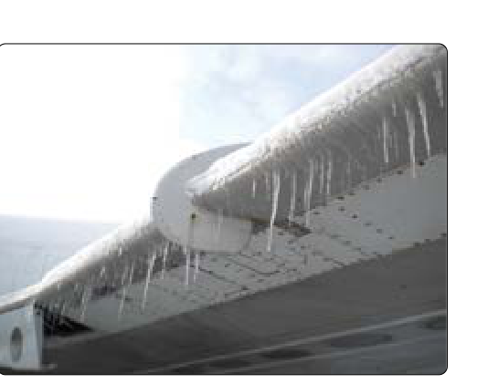
Ice on aircraft surfaces is one of the most insidious hazards in flight, and among its many forms, runback ice stands out as particularly deceptive. Unlike the frost that accumulates on a parked airplane or the rime ice that builds visibly on an unprotected leading edge, runback ice forms precisely because an anti-icing or deicing system is partially working. Water that has been warmed or shed by a protected zone flows aft, then refreezes on surfaces that receive no heat at all — creating a ridge or horn of ice in a location where pilots and designers may not expect it. Understanding how this happens, why it matters aerodynamically, and how modern systems are engineered to prevent it is essential knowledge for any airframe technician working on ice and rain control systems.
The FAA's Aviation Maintenance Handbooks and the Pilot's Handbook of Aeronautical Knowledge both emphasize that effective ice protection requires a systems-level perspective. No single component can be evaluated in isolation. Runback ice is the clearest example of why: a leading-edge thermal anti-ice system that functions perfectly within its design limits can still allow dangerous ice accumulation if the aft extent of the heated zone is insufficient or if the aircraft is operated outside the system's certification envelope.
How Runback Ice Forms
To understand runback ice, start with the icing environment itself. When an aircraft flies through a cloud containing supercooled liquid water droplets (SLWDs), those droplets remain liquid below 0 °C because they lack a nucleus around which to freeze. The moment they strike a surface, the impact provides that trigger, and they begin to freeze. In rime icing conditions — cold temperatures, small droplets — freezing is nearly instantaneous, and the water stays put. In glaze or clear icing conditions — temperatures closer to 0 °C or larger droplets — only part of each droplet freezes on impact. The remaining unfrozen water, called runback water, flows aft along the surface under aerodynamic forces.
On an aircraft equipped with a thermal anti-ice system (such as bleed-air heated leading edges), the protected zone is designed to keep the leading edge warm enough to evaporate or shed impinging water. In fully evaporative operation, all impinging water is evaporated before it can run aft — no liquid water leaves the heated zone. In running wet operation, the system intentionally allows liquid water to flow beyond the parwan zone because full evaporation would require more energy than the system can supply. That liquid water travels aft into the unheated region of the wing or empennage, where it eventually refreezes. The resulting deposit — the runback ice — typically forms as a ridge or horn several inches aft of the leading edge, often near the spanwise extent of the heated panel.
The shape of runback ice is critically important. Because the water has already passed the stagnation point and is flowing on the lower or upper surface, it tends to freeze in a shape with a sharp, protruding horn rather than the smooth mound of rime ice. This horn can be located at the 10–15% chord position on the upper surface — precisely where it can trigger early boundary layer separation. Modern large-droplet icing environments, associated with Supercooled Large Droplets (SLDs) such as freezing drizzle or freezing rain, dramatically worsen the runback problem because the droplets carry far more water mass and can travel much farther aft before freezing.
The SLD Threat and Appendix O
Conventional icing certification was historically based on the droplet size distributions defined in 14 CFR Part 25, Appendix C. Research accumulated over decades — including data from accident investigations — demonstrated that SLD environments could produce runback ice accumulations far outside what Appendix C envelopes anticipated. In response, the FAA issued regulations expanding certification requirements. 14 CFR Part 25, Appendix O defines SLD icing conditions, including freezing drizzle (droplet median volume diameters up to 500 micrometers) and freezing rain. Aircraft certified for flight in SLD conditions under Appendix O must demonstrate that runback ice accumulations in those environments do not cause unacceptable handling characteristics or loss of control margins. Airframe technicians maintaining aircraft with SLD-rated ice protection systems must be familiar with these distinctions, because the system architecture — heated zone length, power levels, and detection logic — differs from older Appendix C-only designs.
Thermal Anti-Ice Systems and Runback Prevention
The primary engineering approach to runback prevention is to ensure the heated zone extends far enough aft that runback water either evaporates before leaving the zone or freezes in a benign, low-profile location. System designers balance two competing constraints: extending heat further aft reduces runback but demands more bleed air or electrical power, increasing engine load and fuel burn.
On bleed-air systems, hot compressed air is ducted from the engine compressor stages through piccolo tubes — perforated spanwise tubes inside the leading-edge structure — that direct high-velocity hot air against the inner skin. The aft boundary of the heated zone is determined by the piccolo tube placement and the thermal conductivity of the structure. Technicians inspecting these systems must verify piccolo tube integrity (no blockage or cracks), proper bleed air pressure and temperature at the inlet, and the condition of the seals that prevent hot air from escaping into unintended areas, all of which affect the effective heated zone boundary and thus runback behavior.
On electrically heated systems, heating elements are embedded in the leading-edge skin or bonded to it. These systems offer more precise zone control but are limited by the aircraft's electrical generating capacity. Some designs use a cyclic (deicing) mode rather than continuous anti-icing, allowing ice to build then shedding it in cycles. In cyclic systems, runback is an inherent part of the shedding process: meltwater flows aft and must be accounted for in the certification basis. Technicians must ensure heating element continuity, proper resistance values (per the Aircraft Maintenance Manual), and that no element failures have created cold spots that allow excessive runback accumulation.
Pneumatic Deicing Boots and Runback Interaction
Pneumatic deicing boots — the inflatable rubber bladder systems common on turboprops and piston twins — operate differently from thermal systems, and their interaction with runback deserves specific attention. Boots crack and shed ice mechanically; they do not heat the surface. When a boot cycles and breaks the ice, meltwater is not produced, so classical thermal runback is not the primary concern. However, in warm icing conditions where impacting water is not fully freezing on the boot surface, liquid water can still flow aft onto the unprotected area behind the boot and refreeze there. Additionally, if a boot is activated too early — before the ice has built to sufficient thickness — it may crack only the outer layer, leaving a residual ice layer that is bonded tightly and very difficult for subsequent cycles to remove. This residual ice effectively extends the iced zone aft, mimicking a runback pattern. Technicians must verify boot inflation pressure, timing, and the condition of the boot material (no debonding, cracks, or hardening) to ensure the system sheds ice cleanly and completely.
Why Runback Ice Matters: Aerodynamic Consequences
The aerodynamic penalty of runback ice is disproportionate to its size. Wind tunnel research documented in FAA technical reports has demonstrated that a runback ice horn as shallow as a fraction of an inch at the 10–15% chord location can reduce maximum lift coefficient by 30% or more and dramatically reduce the angle of attack at stall. The stall may become more abrupt and may occur with less warning buffet than the pilot expects. On the empennage, runback ice on the horizontal stabilizer can trigger a tailplane stall — a particularly dangerous event because the pilot's instinctive response (back pressure to recover from a nose-down upset) is exactly wrong. Flap extension increases the download on the tail, and if the tailplane is already marginally stalled due to runback ice, the result can be an unrecoverable pitch-over.
Key Numbers and Rules
- Appendix C (14 CFR Part 25): Traditional icing envelope; droplets generally up to 50 micrometers MVD — the historical certification baseline.
- Appendix O (14 CFR Part 25): SLD icing envelope, covering freezing drizzle (up to ~500 μm MVD) and freezing rain; runback behavior is significantly more severe.
- Piccolo tube inspection intervals: Per the individual Aircraft Maintenance Manual; blockage as small as one hole can create a cold spot and localized runback accumulation.
- Heating element resistance checks: Resistance values must be within the AMM tolerance band — an element running too cool due to high resistance allows runback; one too hot risks structural damage.
- Boot inflation pressure: Typically specified in PSI per the AMM; under-inflation leads to incomplete cracking and residual ice that mimics runback patterns.
- Icing certification flight tests: Aircraft must demonstrate compliance with acceptable handling qualities after runback accumulations in both Appendix C and (if applicable) Appendix O environments.
Common Test Traps
- Assuming anti-ice means no icing hazard aft of the boots or heaters. Runback ice can form on completely unprotected surfaces downstream of a working system — the system's protection zone has a physical boundary.
- Confusing deicing and anti-icing in the context of runback: anti-icing (continuous heat) can be designed to evaporate runback; deicing (cyclic boots) does not heat the surface and relies on mechanical shedding, so residual ice patterns differ.
- Overlooking tailplane runback. Horizontal stabilizer icing — including runback — is often tested because it leads to tailplane stall, whose recovery (pushing forward on the yoke, reducing flaps) is counterintuitive and safety-critical.
- Ignoring SLD environments. A system certified only to Appendix C provides no assurance of adequate protection — including runback control — in freezing drizzle or freezing rain (Appendix O conditions).
- Neglecting maintenance of the boundary of the heated zone. Damaged seals, cracked piccolo tubes, or failed heating elements change where the protected zone ends, altering where runback ice forms — a fact frequently tested in AMT airframe written questions about ice protection system inspection.