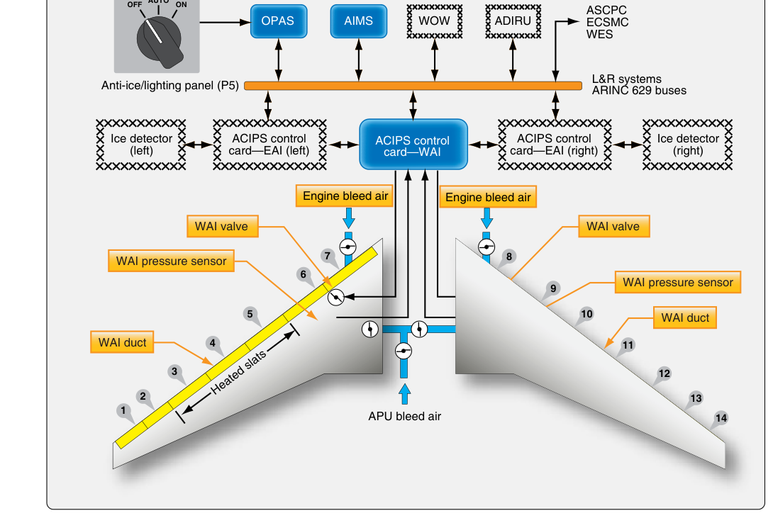
Ice accumulation on a wing's leading edge is one of the most serious threats in aviation. Even a thin, rough layer of ice can disrupt the smooth airflow over the wing, reduce lift, increase drag, and in severe cases cause a stall at speeds well above the normal stall speed. To combat this hazard, transport-category and many turbine-powered aircraft use a thermal anti-icing (TAI) system that continuously supplies hot air to the wing leading edge, keeping skin temperatures high enough that moisture cannot freeze on contact. Unlike de-icing systems, which allow ice to form and then shed it, anti-icing systems are proactive — they prevent ice formation in the first place. For the Aviation Maintenance Technician (AMT) working on airframe systems, a thorough understanding of how bleed-air TAI systems are designed, operated, inspected, and troubleshot is essential for both the FAA Knowledge Test and safe return-to-service work.
Source of Bleed Air
The heat energy in a bleed-air TAI system comes from compressed air extracted — or "bled" — from an intermediate or high-pressure stage of the engine's compressor section. Turbine engines produce prodigious quantities of hot, high-pressure air as a byproduct of the compression cycle. Tapping a small fraction of this air for thermal management systems is efficient because the air is already compressed and heated; no separate heating element or combustion source is needed. Actual bleed air temperatures and pressures delivered to the wing anti-ice system vary considerably by aircraft type, engine model, and the bleed stage selected, so technicians should always consult the specific Aircraft Maintenance Manual and type-certificate data rather than relying on a general figure. Because these temperatures are high enough to damage structure or systems if uncontrolled, precise regulation is mandatory.
How the System Works
Bleed air is routed from the engine through a series of ducting, valves, and regulators before it reaches the wing leading edge. Understanding this flow path is the key to AMT-level comprehension of the system.
Pressure Regulation and Shutoff Valves
Immediately downstream of the bleed air port, a pressure-regulating and shutoff valve (PRSOV) performs two functions: it reduces the raw bleed air pressure to a value appropriate for downstream ducting, and it can completely shut off flow on command — either by the crew for system isolation or automatically on detection of a duct leak or overheat. Downstream of the PRSOV, a flow control valve or modulating valve may further fine-tune airflow to maintain consistent anti-icing performance across a range of engine power settings. These valves are typically pneumatically actuated, with electrical control signals commanding open or closed positions. Their position is usually annunciated in the cockpit so the crew knows whether anti-ice is truly flowing.
Distribution in the Leading Edge
Once regulated bleed air enters the wing, it is directed into a piccolo tube (also called a spray tube or piccolo duct) — a long, slender tube running spanwise inside the leading edge. The piccolo tube has rows of small holes or slots drilled along its length that direct jets of hot air directly against the inside surface of the leading edge skin. This impingement heating is highly effective because the high-velocity air jets strip away the boundary layer of cooler air that would otherwise insulate the metal skin, allowing very efficient heat transfer. After impinging on the skin, the air flows rearward through the leading edge cavity and is exhausted overboard through ports typically located at the lower surface of the wing, or in some designs through the wheel well area. This exhaust must be directed carefully to avoid aerodynamic interference and to prevent hot air from re-entering nacelles or other sensitive areas.
Temperature Sensing and Overheat Protection
Because the leading edge skin is an aluminum or composite structure with temperature limits, overheat detection is a critical safety feature. Temperature sensors — thermocouples or thermistors — are bonded to or embedded in the leading edge structure at representative locations. If skin temperature exceeds a design threshold, the system automatically reduces flow or commands the shutoff valve closed and illuminates a cockpit warning. Some aircraft also use duct overheat sensors along the supply ducting itself; these are often continuous-element pneumatic or electric sensing loops that detect a duct rupture or leak that would allow hot air to impinge on surrounding structure.
System Configurations: Continuous vs. Cyclic
Most bleed-air wing TAI systems operate in a continuous mode: whenever the anti-ice switch is selected ON and the aircraft is in icing conditions (or anticipated icing conditions), hot air flows constantly. This is distinct from pneumatic or electrothermal de-icing boot systems that cycle on and off. Continuous heating ensures that no ice is allowed to initiate at any point on the protected surface. Some aircraft designs do incorporate a modulated approach where the flow valve adjusts heating intensity based on temperature feedback, balancing thermal protection against the thermodynamic penalty of extracting bleed air from the engines — a penalty that reduces available thrust and increases fuel consumption. The AMT must understand what the aircraft's maintenance manual specifies as normal system behavior when evaluating system performance during ground testing.
Protected Surfaces
On most transport-category aircraft, the bleed-air TAI system protects only the wing leading edge slat panels or fixed leading edge areas that are most critical to lift generation. Protection is typically applied to the inboard and outboard leading-edge slat sections identified as critical through the aircraft's icing certification analysis, based on the specific wing design and airflow characteristics of that aircraft type. Some designs also supply bleed air to the horizontal stabilizer leading edge and engine nacelle inlets, though these may use separate control loops. Trailing edge flaps, ailerons, and most of the wing upper and lower surfaces are generally not heated, as ice accumulation in those areas is far less critical or is addressed by other means.
Why It Matters: Safety and Regulatory Context
The FAA requires that aircraft certificated for flight into known icing (FIKI) demonstrate compliance with the icing envelope defined in 14 CFR Part 25, Appendix C (and, for supercooled large drop (SLD) icing conditions such as freezing drizzle and freezing rain, Appendix O). The anti-icing system must keep critical surfaces free of ice throughout that envelope. For the AMT, this regulatory background means that any repair, modification, or component replacement on the TAI system must be accomplished strictly in accordance with the Aircraft Maintenance Manual (AMM) and, where applicable, FAA-approved data, because any degradation of system capability affects the aircraft's certification basis. Flying with an inoperative TAI system is governed by the aircraft's Minimum Equipment List (MEL) and may prohibit flight into known or forecast icing conditions entirely.
Key Numbers and Rules
- Bleed air temperatures: Delivered to the leading edge structure at temperatures that vary by aircraft type and bleed stage; skin temperature limits are defined by the AMM and must not be exceeded.
- Piccolo tube hole sizing: Hole diameter and spacing are precisely engineered for a specific aircraft design; never substitute alternate tubing or drill out holes without approved data.
- Shutoff valve test: Most AMMs require operational testing of the PRSOV open/close function and position indication as part of the anti-ice system functional check after maintenance.
- Duct leak detection: Continuous-loop overheat detectors (such as Fenwal or Kidde-type sensing elements) must be inspected for kinks, corrosion, and secure attachment per the inspection interval in the AMM.
- Ground testing limitation: Bleed-air anti-ice systems must generally be tested only briefly on the ground because prolonged operation without airflow over the wing can cause leading edge overtemperature; follow AMM time limits strictly.
- 14 CFR Part 25 Appendix C: Defines the icing certification envelope (droplet size, liquid water content, temperature range) that the TAI system must address for type certification; Appendix O addresses supercooled large drop (SLD) icing conditions.
Common Inspection and Troubleshooting Points
During scheduled inspections, AMTs focus on several areas where bleed-air TAI systems are prone to problems. The supply ducting, which operates under high temperature and pressure cycling, is susceptible to duct wear and chafing where it passes through structure. Clamps and hangers must be secure and correctly torqued; a loose duct can vibrate against surrounding structure and eventually fail, releasing hot air into an area not designed to contain it. The piccolo tube itself should be inspected for blockage of its jet holes — contamination by insects, dirt, or debris during ground operation can reduce heating effectiveness without triggering any cockpit warning. Valve seats and actuators must be checked for proper travel and positive shutoff, as a valve that does not fully close can cause constant bleed air loss, and one that does not fully open provides inadequate protection. Thermocouples and overheat sensing loops should be continuity-checked and inspected for physical damage. Finally, the exhaust exit ports must be clear of obstructions and free of corrosion that could restrict outflow and increase back-pressure in the leading edge cavity.
Common Test Traps
- Anti-icing vs. de-icing confusion: Thermal bleed-air systems are anti-icing (prevent formation); pneumatic boots are de-icing (remove after formation). The FAA test will probe this distinction directly.
- Ground test time limits: Students often overlook that prolonged ground operation of wing anti-ice can overheat the leading edge; always reference the AMM for maximum ground test duration.
- Piccolo tube direction: Jets impinge directly on the inside of the leading edge skin — the air does not simply fill the cavity and heat by convection alone. Impingement is the key heat-transfer mechanism.
- Bleed air penalty: Extracting bleed air reduces engine thrust and increases fuel burn. On some aircraft, selecting wing anti-ice ON requires advancing throttles to compensate — an operational factor with maintenance-test implications.
- Valve position indication: A cockpit indication of "anti-ice ON" means the switch is selected; it does not always confirm that the valve is actually open and air is flowing. Separate valve position lights or flow indications may be required to confirm actual system operation.