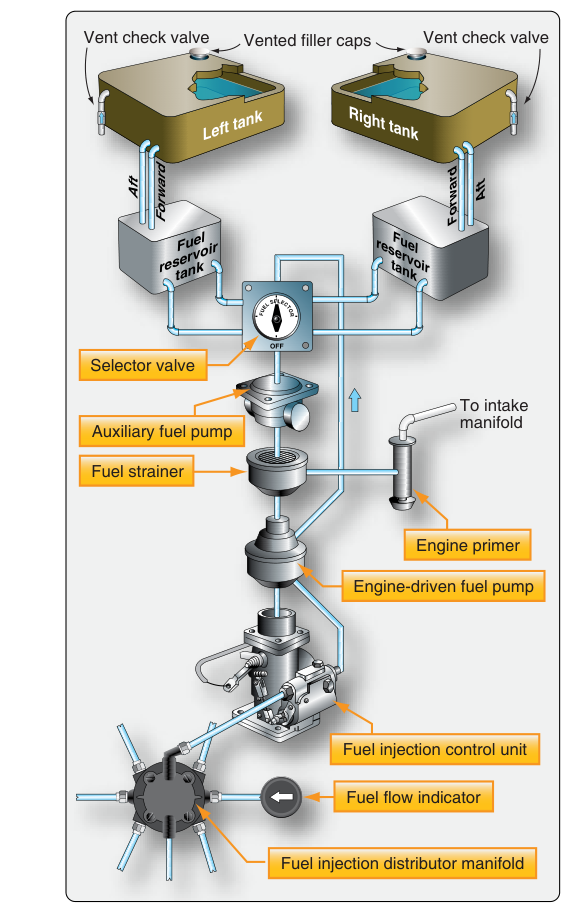
When an aircraft engine produces significantly more power per displacement than a standard normally-aspirated design, the fuel system must keep pace with every demand that increased performance places on it. High-performance and turbocharged piston engines share many components with their simpler cousins, but the pressures, temperatures, flow rates, and control strategies involved are considerably more demanding. For an Aviation Maintenance Technician (AMT) working on powerplants, understanding these differences is not just a test requirement—it is a prerequisite for safe maintenance, troubleshooting, and return-to-service work.
This article focuses on the fuel system considerations unique to high-performance naturally aspirated and turbocharged reciprocating engines, grounded in FAA powerplant maintenance handbook guidance. We will examine why these systems behave differently, what components manage the added complexity, and how common failure modes present themselves during inspection and ground runs.
What Makes These Fuel Systems Different
A high-performance engine—generally considered any certificated engine producing more than 200 horsepower, or one equipped with a constant-speed propeller—already requires more precise fuel metering than a simple fixed-pitch, low-power trainer. Add a turbocharger or turbonormalizer to the equation and you introduce an entirely new set of variables: elevated induction air temperatures, higher manifold pressures, denser charge air (or charge air cooling), and combustion chamber conditions that demand carefully controlled fuel-air ratios across a far wider operating envelope.
In a normally aspirated engine, manifold pressure decreases as altitude increases, naturally reducing the mass of air entering the cylinders. The fuel metering system accounts for this relationship through mixture control. A turbocharged engine, by contrast, can maintain sea-level or even above-sea-level manifold pressure at altitude. Without corresponding fuel system compensation, the mixture would lean dangerously as the turbocharger pushes more air mass through the engine. The fuel system must therefore respond not just to throttle position but to actual air density and mass airflow.
Fuel Injection vs. Carburetion in High-Performance Designs
Most high-performance and virtually all turbocharged certificated piston aircraft engines use continuous-flow fuel injection rather than float-type carburetors. The FAA Aviation Maintenance Handbook—Powerplant (FAA-H-8083-32) explains that fuel injection systems meter fuel based on air mass flowing through the throttle body, delivering it directly to each cylinder's intake port. This approach offers several advantages critical to high-performance operation:
- Elimination of carburetor ice risk: Because fuel is not vaporized in the throttle body, the temperature drop that causes carburetor icing does not occur at the point of air metering. Turbocharged induction systems running hot air are especially vulnerable to carburetor ice if carbureted designs were used, so injection sidesteps this entirely.
- Consistent fuel distribution: Each cylinder receives a metered, individual fuel flow rather than sharing a common charge. This is vital in high-performance engines where even slight cylinder-to-cylinder mixture variations can cause detonation or preignition in one cylinder while others run normally.
- Better power response: Injection systems respond more quickly to throttle changes, reducing the risk of momentary lean excursions during power additions—a particular concern with turbocharged engines where power changes can be abrupt.
Common injection system designs found on turbocharged Lycoming and Continental engines include the RSA (Regulator/Servo/Atomizer) fuel injection system and the Bendix/Precision RSA series. These systems use a servo regulator that senses both throttle position and air mass, modulating fuel pressure to the flow divider and injector nozzles accordingly. The flow divider (also called a manifold valve) ensures even distribution to all cylinders and provides a positive fuel cutoff when the engine is shut down to prevent post-shutdown fuel dribbling.
Turbocharger-Specific Fuel System Considerations
The turbocharger's job is to compress induction air, allowing the engine to ingest more air mass per intake stroke than ambient pressure would otherwise allow. This has direct consequences for the fuel system:
Fuel Flow at High Manifold Pressure
Because the engine consumes more air mass at high manifold pressure, it also requires a proportionally higher fuel flow. Fuel pumps and fuel lines on turbocharged installations are sized for higher flow rates than comparable normally aspirated engines. The engine-driven fuel pump must supply adequate pressure and volume across the full power range, including takeoff at maximum manifold pressure. Boost pumps (electric auxiliary pumps) are standard equipment and are typically required for takeoff and landing on turbocharged aircraft. The AMT must verify that pump output pressures meet the engine manufacturer's specifications, as a pump delivering marginal flow on a normally aspirated engine may be critically inadequate on a turbocharged one.
Fuel Pressure References and Differential Pressure
Many turbocharged fuel injection systems reference fuel pressure differentially—that is, fuel pressure is measured relative to the pressure inside the induction system (manifold pressure) rather than absolute atmospheric pressure. This is crucial because as manifold pressure increases above ambient, a fixed fuel pressure would result in reduced differential pressure across the injector nozzles and lower actual fuel flow. Differential pressure sensing ensures that as manifold pressure rises, the metered fuel pressure rises proportionally, maintaining the correct fuel-air ratio. Technicians must understand which reference port (atmospheric or manifold) is used when troubleshooting fuel flow indications on a specific installation.
Charge Air Cooling and Its Effect on Mixture
Many turbocharged installations include an intercooler (also called a charge air cooler) between the turbocharger compressor outlet and the throttle body. Cooling the compressed air increases its density, allowing more air mass into the cylinders. A denser charge requires more fuel to maintain the correct mixture ratio. The fuel metering system must account for this. If an intercooler is bypassed or fails, the hotter, less dense induction air entering the engine means less air mass is available for a given fuel flow—so if the pilot uses the same power setting and fuel flow numbers, the mixture will be richer than intended, not leaner. AMTs must ensure intercoolers are inspected for internal leaks, core damage, and bypass valve operation as part of any fuel system troubleshooting related to mixture irregularities.
Vapor Lock in High-Performance and Turbocharged Systems
Vapor lock occurs when fuel vaporizes inside fuel lines or the fuel pump before it reaches the metering system, interrupting liquid fuel flow. High-performance engines are more susceptible for several reasons: higher operating temperatures (particularly in turbocharged installations where the engine compartment runs hot), higher fuel flow velocities that can cause localized pressure drops, and fuel line routing that may expose lines to heat soak after engine shutdown (hot start conditions). The FAA handbook notes that vapor lock most commonly occurs during hot restart attempts and during ground operations in high-density-altitude, high-temperature conditions.
Turbocharged installations often route fuel lines through particularly hot areas of the cowling. The electric boost pump is the primary defense: it maintains positive fuel pressure in the lines, suppressing vaporization. Insulation and heat shielding on fuel lines in high-temperature zones is also specified by the aircraft manufacturer and must be maintained in serviceable condition. An AMT finding cracked or missing fuel line insulation near turbocharger components should treat this as an airworthiness concern, not a cosmetic deficiency.
Mixture Management and Enrichment Circuits
High-performance engines may incorporate automatic mixture control (AMC) systems or altitude-compensating fuel pumps that adjust fuel flow as altitude changes without pilot intervention. Turbocharged installations sometimes use an enrichment circuit that provides additional fuel flow at high power settings to provide both mixture correctness and combustion cooling—preventing detonation and managing cylinder head temperatures (CHTs). These enrichment circuits are often part of the servo regulator design. If an enrichment circuit malfunctions and fails to provide the additional fuel at high power, the engine may overheat or detonate at high manifold pressure settings even at what appears to be a normal mixture control position.
Key Numbers and Rules
- Fuel injection system operating pressure: Specific values vary by engine model; always reference the applicable engine manufacturer's maintenance manual. Typical unmetered fuel pressures on Lycoming and Continental turbocharged engines range from approximately 14 to 45 PSI depending on engine model and power setting—always verify against the specific manual.
- Boost pump requirement: Most turbocharged aircraft require the electric boost pump ON for all takeoffs, landings, and any time manifold pressure exceeds a specified value. This is specified in the AFM/POH and engine installation data.
- Fuel-air mixture ratio: Stoichiometric (chemically correct) combustion occurs at approximately 15:1 air-to-fuel ratio by weight. Best power is typically achieved around 12.5:1 and best economy near 15.5:1. High-performance engines operating rich of peak (ROP) for detonation margin on high-power operations run richer than stoichiometric.
- Detonation risk: Excessively lean mixtures at high manifold pressure are the primary fuel-system-related cause of detonation. Fuel flow gauges, CHT gauges, and exhaust gas temperature (EGT) gauges work together—an AMT must verify all are calibrated and operative.
- Injector nozzle inspection: FAA guidance recommends inspecting and cleaning injector nozzles at specified intervals. Clogged nozzles cause cylinder-to-cylinder fuel flow imbalance, which is especially dangerous in turbocharged engines at high power.
Common Test Traps
- Assuming carbureted = high performance: Most high-performance and all turbocharged certificated piston engines use fuel injection, not carburetors. Selecting a carburetor-related answer for a turbocharged engine question is a classic trap.
- Ignoring differential pressure referencing: A question may describe a fuel flow that seems correct by absolute pressure but is actually lean because manifold pressure is elevated. Remember that turbocharged injection systems often reference induction pressure, not atmospheric.
- Confusing enrichment circuit failure symptoms: Detonation or high CHTs at full power despite normal mixture control position can indicate an enrichment circuit failure, not a pilot error. Test questions may attribute this to mixture control position rather than the enrichment system.
- Vapor lock as only a hot-soak problem: While hot starts are the classic vapor lock scenario, high-temperature ground operations and high-density-altitude departures can also produce vapor lock in flight. Don't eliminate vapor lock as a diagnosis just because the engine was cold-started.
- Overlooking intercooler condition: An intercooler with an internal leak allows manifold pressure to bleed into the fuel system reference line or allows unmetered air into the induction system—both affect mixture accuracy. The test may describe a symptom (erratic fuel flow, rich mixture at altitude) that traces to the intercooler, not the fuel metering unit itself.