Every time an aircraft touches down, the wheel and brake assembly absorbs tremendous kinetic energy and converts it into heat, all within seconds. For aviation maintenance technicians (AMTs) working on airframe systems, a thorough understanding of wheel and brake assembly components is not optional — it is a core safety responsibility. Whether you are overhauling a Cessna 172's simple single-disc brake or inspecting the multi-disc carbon brake stack on a transport-category aircraft, the fundamental components and their functions follow consistent engineering logic grounded in FAA guidance and manufacturer data.
This article walks through each major component of a typical aircraft wheel and brake assembly, explains how the parts work together, and highlights the inspection and maintenance considerations that keep these systems airworthy. The Aviation Maintenance Technician Handbook — Airframe (FAA-H-8083-31) serves as the primary FAA reference for this topic, and its coverage of landing gear systems forms the backbone of what follows.
The Aircraft Wheel: Structure and Components
Aircraft wheels differ significantly from automotive wheels. They must withstand not only static weight but also the sudden shock loads of landing, the heat generated by braking, and the stresses of inflation pressure from high-pressure tires. Most general aviation and transport aircraft use split-wheel (two-piece) construction, meaning the wheel is made of two halves — an inboard half and an outboard half — bolted together. This design allows the tire to be mounted and dismounted without the need to break a bead in the traditional sense; instead, the wheel halves separate.
Wheel Halves and Flanges
Each wheel half is typically forged or cast from aluminum alloy, providing a high strength-to-weight ratio. The mating flanges of the two halves are precision-machined and secured with a series of through-bolts and nuts, which must be torqued to manufacturer specifications. Uneven or incorrect torque can warp the flanges, leading to air leaks or structural failure under load. A fusible plug (discussed below) is usually threaded into the wheel half to provide overpressure protection.
Bearings
The wheel rotates on tapered roller bearings or, in lighter aircraft, ball bearings. These bearings are seated in bearing cups (races) pressed into the wheel hub. Proper lubrication of bearings is critical — the correct grease type and quantity must be applied during reassembly. Over-greasing can cause heat buildup, while under-greasing leads to premature wear. Bearing preload and end-play are checked during installation to ensure smooth rotation without excessive slop or binding.
Fusible Plugs
A fusible plug is a safety device threaded into the wheel. It contains a core of low-melting-point alloy designed to melt and release tire pressure if wheel temperature reaches a dangerous level — typically caused by heavy or prolonged braking. This controlled deflation prevents a tire blowout, which could cause far more catastrophic structural damage to the aircraft and create a serious hazard for ground personnel. Fusible plugs must be inspected regularly and replaced if the core has partially melted or if there is any question about their integrity.
Valve Stem and Tire Interface
The valve stem, usually a metal tubeless type, is integral to the wheel half and allows the tire to be inflated to the specified pressure. Aircraft tire pressures are considerably higher than automotive tires — many general aviation tires operate in the range of 50 to over 200 psi depending on aircraft type. Only dry nitrogen (or in a pinch, dry air) should be used to inflate aircraft tires, because pure oxygen accelerates rubber degradation and creates a fire hazard in the presence of tire compounds and lubricants.
The Brake Assembly: Types and Components
Aircraft brakes are hydraulically actuated friction devices. Most modern aircraft use disc-type brakes because of their superior heat dissipation and consistent performance. The two broad categories are single-disc and multiple-disc designs.
Brake Disc (Rotor)
The brake disc, also called the rotor, is attached to and rotates with the wheel. On single-disc systems common in general aviation, one disc is keyed to the wheel so that it spins with the wheel but can slide slightly inward and outward along the axle axis to allow for clamping. Discs are typically made from steel or, in high-performance applications, carbon composite materials. Carbon brakes offer reduced weight and excellent heat capacity but require specific inspection procedures because damage manifests differently than in steel discs. The disc must be inspected for warping, cracks, minimum thickness (wear limit), and scoring. A disc that has worn below its minimum serviceable thickness must be replaced — no exceptions.
Brake Caliper
The caliper is the stationary portion of the brake assembly, bolted to the landing gear strut or axle flange. It houses the hydraulic pistons and holds the brake lining (pucks or pads) that clamp against the disc. When the pilot depresses the brake pedals, hydraulic fluid pressure is directed into the caliper, driving the pistons outward and pressing the linings against the rotating disc. The friction generated slows the disc and, therefore, the wheel.
Calipers are inspected for cracks, corrosion, piston seal leaks, and proper piston retraction. A piston that does not fully retract after brake release causes brake drag, which generates excessive heat, accelerates lining wear, and can lead to a brake fire on long taxi or takeoff runs.
Brake Linings (Pads or Pucks)
Brake linings are the sacrificial friction material that contacts the disc. In aviation, these are often organic, sintered metallic, or carbon composite materials depending on the application. Linings must be inspected for minimum thickness, uneven wear, cracking, glazing, and contamination. Hydraulic fluid or grease contamination of a brake lining dramatically reduces friction effectiveness and is cause for replacement. Lining wear indicators (pins or witness marks) on many assemblies allow quick visual assessment of remaining lining material without full disassembly.
Hydraulic Actuating Cylinders and Seals
Each caliper piston is sealed with O-ring or lip-type seals that must withstand high hydraulic pressure and elevated temperatures. Seal degradation leads to external leaks (visible at the brake assembly) or internal bypass, reducing braking force. Seals are replaced during overhaul or whenever there is evidence of leakage. The correct seal material must be used — seals compatible with MIL-PRF-5606 (petroleum-based) fluid are not interchangeable with those designed for MIL-PRF-87257 or Skydrol (phosphate ester) fluid systems.
Bleeder Valves
Each caliper incorporates a bleeder valve (bleeder screw) that allows air to be purged from the brake hydraulic system. Air is compressible; even a small air bubble in the brake line produces a spongy pedal feel and reduced braking force. Proper brake bleeding — either pressure bleeding from the reservoir down or gravity/suction bleeding from the caliper up — ensures a firm, responsive pedal. The bleeder valve is inspected for correct sealing and must be replaced if damaged or if the soft tip is deteriorated.
Multiple-Disc Brake Systems
Transport-category aircraft and high-performance turboprops use multiple-disc (or multi-puck) brake assemblies to handle the much greater kinetic energy involved. These systems feature alternating rotating discs (keyed to the wheel) and stationary discs (keyed to the torque tube, which is fixed to the axle). A pressure plate and backing plate complete the stack. When hydraulic pressure is applied, the entire stack is compressed together, with friction occurring at every disc interface — multiplying the braking force compared to a single disc. The torque tube, which anchors the stationary discs, is a critical structural component and must be inspected for cracks, fretting, and corrosion.
Anti-Skid Systems
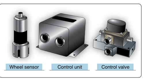
Modern aircraft, from advanced piston singles to airliners, may be equipped with anti-skid systems that prevent wheel lockup during braking — the aircraft equivalent of an automotive ABS. Wheel speed sensors (transducers) on each wheel continuously send electrical signals to an anti-skid control unit. If the control unit detects a wheel decelerating faster than the deceleration rate consistent with normal rolling friction (a sign of impending skid), it momentarily releases hydraulic brake pressure to that wheel, allowing it to spin back up before reapplying pressure. This cycle happens many times per second. Benefits include maximum braking efficiency, prevention of tire blowouts from skidding, and reduced tire wear. Touchdown protection and locked-wheel protection are additional sub-functions of many anti-skid systems.
Key Numbers and Inspection Limits
- Disc thickness: Must meet the manufacturer's minimum serviceable thickness. There is no universal number — always consult the aircraft's maintenance manual or component overhaul manual.
- Brake lining minimum thickness: Manufacturer-specified; many systems use wear pins that, when flush with the housing, indicate replacement is required.
- Bearing preload and end-play: Set per manufacturer specification during assembly; incorrect adjustment causes bearing failure.
- Nitrogen inflation: Dry nitrogen is the required inflation medium for aircraft tires; oxygen or shop air containing moisture is not acceptable.
- Hydraulic fluid compatibility: Seals, hoses, and fluid must be of compatible types — never mix petroleum-based and phosphate ester fluids.
- Torque values: Wheel bolt and caliper fastener torque must follow the manufacturer's maintenance manual; under- or over-torque compromises safety.
Why It Matters: Safety and Airworthiness
Brake system failures are among the most consequential landing-phase malfunctions. A dragging brake can ignite a tire fire; a complete brake failure on rollout can result in a runway excursion. Worn discs, contaminated linings, or air in the system can all silently degrade braking performance without obvious external signs until the pilot presses hard on the pedals during a rejected takeoff or a short-field landing. AMTs who understand each component's function are equipped to catch marginal conditions during routine inspections — before they become emergencies.
Common Test Traps
- Fusible plug purpose: Students sometimes confuse fusible plugs with valve stems. Remember: fusible plugs protect against thermal overinflation, not normal pressure adjustment.
- Inflation medium: The correct answer is always dry nitrogen for aircraft tires — not compressed air and certainly not oxygen.
- Fluid compatibility: Phosphate ester (Skydrol) and petroleum-based (MIL-PRF-5606) systems require different seals and are not cross-compatible — a common distractor on exams.
- Disc wear: There is no single standard wear limit; always reference the specific maintenance manual. Test questions that offer a universal number are traps.
- Anti-skid function: Anti-skid does not apply the brakes; it modulates (releases and reapplies) hydraulic pressure to prevent lockup. Confusing the system's action with a brake booster is a common error.