Retractable landing gear is one of the defining features of higher-performance aircraft, allowing the wheels, struts, and associated hardware to fold neatly away during flight and dramatically reduce parasitic drag. For an aviation maintenance technician (AMT) working on the airframe, a thorough command of how these systems operate — hydraulically, electrically, and mechanically — is indispensable. Every retraction cycle involves a carefully orchestrated sequence of valves, actuators, locks, and indicators, any one of which, if improperly maintained, can create a serious safety-of-flight hazard.
This article covers the core operating principles of retractable landing gear systems, the major component types, safety interlocks, emergency extension methods, and the inspection points most commonly tested on the FAA AMT Airframe Knowledge Exam.
Why Retractable Gear Exists
Fixed landing gear produces continuous aerodynamic drag throughout a flight. On a typical light aircraft, retracting the gear can reduce total drag by 30 percent or more, translating directly into higher cruise speed and improved fuel economy. For transport-category aircraft, the benefit is even more pronounced. The trade-off is mechanical complexity: retractable systems require actuators, position sensors, uplocks, downlocks, squat switches, warning systems, and provisions for emergency extension — all of which must be maintained to exacting standards.
How Retractable Gear Systems Work
Hydraulic Systems
The most common retraction method on commercial and high-performance general aviation aircraft uses hydraulic power. A hydraulic pump — driven by an engine, an electric motor, or both — pressurizes fluid that is directed through selector valves to hydraulic actuating cylinders attached to each gear leg. When the pilot moves the gear selector to the UP position, pressurized fluid enters the retract port of each actuator and mechanically shortens it, pulling the gear into the wheel well. Simultaneously, fluid from the extend side of the actuator returns to the reservoir through a return line.
Each gear position (up or down) is held by a mechanical lock rather than by continuous hydraulic pressure. This is a critical design principle: hydraulic systems are subject to pressure decay over time, and relying on fluid pressure alone to hold the gear in place would be unsafe. Instead, overcenter linkages or hook-type uplocks and downlocks physically latch the gear at the end of its travel. When the gear is retracted, an uplock hook catches the gear leg or a fitting on it; when extended, a downlock (often a spring-loaded overcenter link) snaps into place to prevent inadvertent collapse.
Electric Systems
Smaller retractable aircraft — many single-engine trainers and light twins — use electric actuators rather than a full hydraulic system. A reversible electric motor drives a screw jack, jackscrew, or a series of cables and push-pull rods to raise and lower the gear. The motor runs in one direction to retract and reverses to extend. Limit switches cut power to the motor when the gear reaches the full-up or full-down position, preventing over-travel. Electric systems are simpler and lighter than hydraulic systems but are limited by the torque available from reasonably sized electric motors, making them best suited for lighter aircraft.
Electro-Hydraulic Systems
Many aircraft combine both technologies in an electro-hydraulic system: an electrically driven hydraulic pump provides hydraulic power only when needed. The pump runs when the selector is moved, builds pressure to actuate the gear, and then stops once the gear locks into position. This approach saves the weight of a continuously running engine-driven hydraulic pump and is common on light twins and business jets.
Key Components and Their Functions
- Selector valve: Directs hydraulic fluid to either the retract or extend side of the actuating cylinders based on cockpit selector position.
- Actuating cylinders (linear actuators): Convert hydraulic pressure into the mechanical force needed to move the gear through its travel arc.
- Uplocks: Mechanical hooks or latches that hold the gear in the retracted position; they must be released (usually by a small hydraulic or electric latch-release mechanism) before the gear can extend.
- Downlocks / overcenter links: Snap into an overcenter position when the gear is fully extended, mechanically preventing the gear from collapsing under load.
- Squat switch (weight-on-wheels switch): Senses whether the aircraft is on the ground; prevents retraction on the ground as a safety interlock.
- Sequence valves: On aircraft with gear doors that must open before the gear moves and close after it retracts, sequence valves ensure events occur in the correct order by restricting flow until upstream pressure reaches a set threshold.
- Priority valves: Ensure hydraulic pressure is allocated to the most critical functions (like brakes or flight controls) if system pressure drops.
- Position indicators: Cockpit lights — typically green for gear down and locked, red or amber for gear in transit or unsafe, and no light (or a dark indicator) for gear up and locked — tell the flight crew the system status.
Gear Door Sequencing
Most retractable gear systems incorporate gear doors that must open before the gear can move and close after the gear is stowed. The sequencing is managed by sequence valves in hydraulic systems or by limit switches controlling relay logic in electric systems. The sequence for retraction is typically: (1) doors open, (2) gear retracts, (3) doors close. Extension reverses this: (1) doors open, (2) gear extends and downlocks, (3) doors close (or remain partially open on some designs). Improper sequencing — caused by a misadjusted sequence valve or a faulty switch — can cause a gear leg to contact a partially opened door, resulting in structural damage.
Warning Systems
Retractable gear aircraft are required to have a landing gear position warning system. The most common implementation is a horn or tone that activates when the throttle is retarded below a certain manifold pressure or throttle position and the gear is not down and locked. Some aircraft couple the warning to flap position as well. The squat switch also plays a role: it typically must indicate weight on wheels before the warning system will inhibit (silence), ensuring that a pilot on approach cannot silence the warning simply by selecting gear-up on the ground.
Emergency Extension Systems
Every retractable gear aircraft must have an independent means of extending the landing gear if the normal system fails. Common emergency methods include:
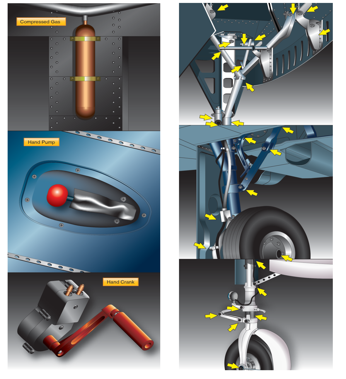
- Manual free-fall (gravity drop): A handle or lever releases the uplocks mechanically; gravity and aerodynamic forces drive the gear down, where it locks over-center. The pilot may need to yaw or pitch the aircraft to help the gear swing into place.
- Pneumatic (nitrogen) bottle: A dedicated bottle of compressed nitrogen is plumbed to the extend side of the actuators. When the emergency handle is pulled, nitrogen pressure forces the gear down and locks it. This system is one-shot and non-rechargeable in flight.
- Auxiliary hydraulic hand pump: A cockpit-mounted hand pump allows the pilot to manually generate hydraulic pressure to extend the gear when the normal pump has failed.
- Electric backup motor: Some aircraft have a secondary electric motor on a separate circuit breaker that can extend the gear if the primary motor or its circuit fails.
After any emergency extension, the gear must be considered down and locked only if the position indicators confirm it. Mechanics must inspect and service the emergency system before the next flight and determine what caused the normal system failure.
Key Numbers and Rules
- Retractable gear aircraft require a landing gear position warning system per 14 CFR Part 23 (and Part 25 for transport category aircraft).
- Hydraulic system operating pressures for general aviation retractable gear systems typically range from approximately 1,000 to 3,000 psi, depending on the aircraft design.
- Gear extension and retraction speed limits are published in the Aircraft Flight Manual (AFM): VLO is the maximum speed at which gear may be operated (raised or lowered), while VLE is the maximum speed at which the aircraft may fly with the gear extended.
- Overcenter downlocks must be rigged so that the linkage passes through center and locks by a specified minimum over-center measurement (per the manufacturer's maintenance manual — typically checked with a straightedge or rigging tool).
- After any system repair, a gear retraction check is performed with the aircraft safely on jacks to verify proper sequencing, full travel, lock engagement, and indicator operation before returning the aircraft to service.
Common Test Traps
- Confusing VLO and VLE: Many students mix these up. Remember: VLO is the limit for gear operation (moving), and VLE is the limit for gear extended (flying with it down). VLO is always equal to or lower than VLE.
- Assuming hydraulic pressure holds the gear: The gear is held in position by mechanical locks (uplocks and downlocks), not by hydraulic pressure. This is a fundamental design principle the exam frequently tests.
- Sequence valve vs. priority valve: Sequence valves control the order of events in a multi-function hydraulic system (like gear and doors); priority valves protect critical systems from pressure loss. They are different components with different purposes.
- Squat switch function: The squat switch prevents gear retraction on the ground and is part of the warning system logic — it does not prevent gear extension, only retraction while weight is on wheels.
- Emergency extension and return to service: After a pneumatic (nitrogen) emergency extension, the bottle must be recharged and the normal system must be inspected and repaired before the next flight. The aircraft is not airworthy for another flight on the emergency system alone.