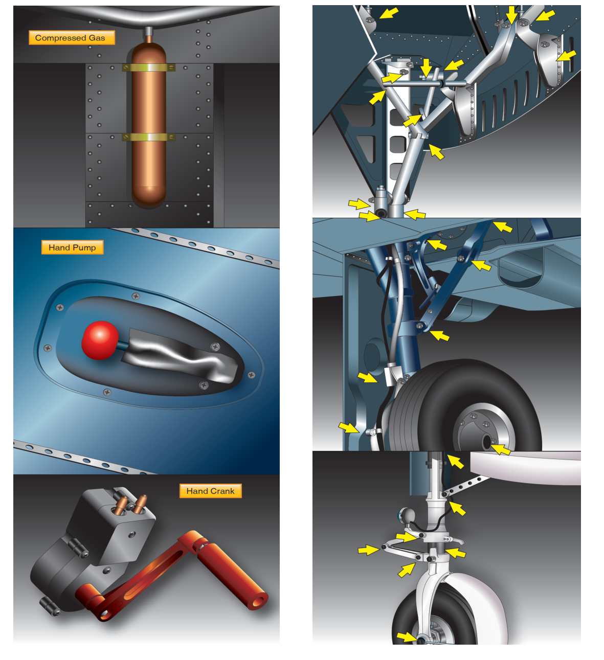
Landing gear is one of the most safety-critical systems on any aircraft. Under normal conditions, a powered hydraulic or electrical system extends and retracts the gear on command. But what happens when that primary system fails? Airplanes certificated with retractable landing gear under the applicable airworthiness standards are required to have a means of extending the gear in an emergency — a backup system that operates independently of the primary power source. Understanding these emergency extension systems is essential knowledge for any Aviation Maintenance Technician (AMT) working on airframe systems, and the topic appears regularly on FAA knowledge exams.
Emergency landing gear extension systems vary widely by aircraft make and model, but they all share the same fundamental goal: get the wheels down and locked before touchdown, even if hydraulic pressure, electrical power, or both have been lost. This article covers the major types of emergency extension systems, how each one works mechanically, why they are designed the way they are, and the testable details every AMT candidate needs to know.
Why Emergency Extension Systems Are Required
The Federal Aviation Regulations require that each retractable landing gear system have a means of emergency extension that is independent of the normal operating system (see, for example, 14 CFR 23.729 and 14 CFR 25.729). This requirement exists because the consequences of landing gear-up are severe: structural damage to the airframe, engine and propeller strikes, fire risk from fuel spills, and potential loss of life. The backup system must be reliable, straightforward to operate under stress, and capable of getting all gear legs fully down and locked without depending on the same component that failed in the first place.
From a maintenance perspective, the AMT must understand not only how these systems are constructed and rigged, but also how to inspect, test, and certify them after any maintenance action. An improperly rigged emergency extension system that fails to lock the gear down is arguably more dangerous than no backup system at all, because it may give a false sense of security.
Types of Emergency Landing Gear Extension Systems
Gravity Free-Fall (Release) Systems
The simplest and most common emergency extension method on light general aviation aircraft is the free-fall or gravity drop system. In this design, the normal system holds the gear retracted against the force of gravity — usually through hydraulic pressure or an overcenter mechanical lock. When an emergency occurs, the pilot or crew releases the uplocks that hold the gear in the retracted position. Gravity and aerodynamic drag then pull the gear down and into the locked position.
The release mechanism typically consists of a cockpit handle or cable connected to the uplock hooks on each gear leg. Pulling the emergency handle mechanically opens these hooks, bypassing all hydraulic and electrical components. The gear falls under its own weight, and a downlock spring or overcenter geometry snaps the gear into the locked-down position. A green indicator light (or a mechanical indicator like a mirror or a visual pin) confirms that the gear is down and locked.
Because free-fall systems rely on gravity, aircraft must be in a nose-low attitude or at reduced airspeed for the system to work reliably — the pilot's operating handbook (POH) will specify the procedure. Maintenance checks on free-fall systems include verifying that uplocks release freely, that downlocks engage positively with the required load, and that all connecting cables are within specified tension limits and show no fraying or corrosion.
Manual Hand Pump Systems
Many hydraulically actuated retractable gear systems use a manual hydraulic hand pump as the backup. When engine-driven hydraulic pump pressure is lost — due to a pump failure, a broken drive, or a fluid leak that has been isolated — the pilot operates a hand pump in the cockpit to build pressure manually and drive the gear actuators to the down-and-locked position.
The hand pump is plumbed directly into the hydraulic system, usually downstream of the engine-driven pump and its associated check valve. The check valve prevents fluid from flowing backward through the failed main pump, so manual pumping builds pressure in the correct direction. The pilot typically alternates between left- and right-hand strokes on a T-handle or wobble pump until the gear indicates down and locked and the pump handle becomes firm, indicating that actuator travel has ended and pressure is holding.
AMT inspection of manual hand pump systems includes checking for fluid leaks at all fittings, verifying that the pump produces the correct pressure rise per a specified number of strokes, and ensuring that the check valve is serviceable. Pump seals deteriorate over time and must be replaced on schedule.
CO₂ Pneumatic Extension Systems
Some aircraft use compressed gas — typically CO₂ or nitrogen — stored in a high-pressure bottle to blow the gear down when the primary system fails. The gas is routed through dedicated lines to the gear actuators, providing enough force to overcome any aerodynamic loads and push the gear to the down-and-locked position.
CO₂ bottles are single-use in most designs: once discharged, the bottle must be replaced or recharged before the system can be used again. This is a critical maintenance consideration — a discharged or undercharged bottle renders the emergency system inoperative. Regulations require the bottle to be at the correct charge pressure (verified by weighing the bottle and comparing it against the manufacturer's specified weight, or by a pressure gauge where installed). Even a small loss of charge, caused by a leaking valve or seal, can make the system unreliable.
In some applications nitrogen is used instead of CO₂, since it remains gaseous rather than partially liquefying at normal operating temperatures, which can give more consistent pressure output in cold weather — a general pneumatic-system design consideration rather than a fixed FAA rule. Both gases must be dry (moisture-free) to prevent corrosion and ice formation inside the lines.
Electrical Motor-Driven Backup Systems
A few aircraft designs use a separate, dedicated electric motor or actuator as the emergency extension means, powered by an independent electrical bus or battery. This is distinct from the normal electrical gear motor — it is a completely separate circuit, often protected by its own circuit breaker and powered from the battery bus rather than the main bus, so that a generator failure or a blown main bus breaker does not disable both the primary and backup systems simultaneously.
On some aircraft, an emergency extension handle mechanically declutches the normal actuator from the gear linkage, allowing the gear to free-fall while simultaneously releasing the uplocks — combining electrical backup with gravity assist.
Key Numbers, Rules, and Inspection Points
- Bottle charge verification: CO₂ and nitrogen emergency bottles must be weighed (not just pressure-checked) to confirm adequate charge; the acceptable weight range is specified in the aircraft maintenance manual (AMM).
- Downlock load testing: After any rigging change, downlocks must be tested to confirm they will hold the gear down against the specified side loads and drag loads — values are aircraft-specific.
- Cable tension: Free-fall release cables must be tensioned within the manufacturer's tolerance; overtensioning can prevent uplock release, while undertensioning can cause accidental release in turbulence.
- Functional test after maintenance: Any work on landing gear systems, including emergency systems, requires a full retraction and extension functional test (often called a gear swing) before return to service.
- Manual pump stroke count: Know the approximate number of pump strokes required to extend the gear per the AMM — an excessive count indicates internal leakage.
- Independence requirement: The emergency system must be independent of the primary system — a single failure cannot disable both.
Why It Matters: Safety and Airworthiness
An emergency landing gear extension system that is not properly maintained is a latent hazard — it will not announce itself until it is desperately needed. Mechanics who understand how each backup system operates are better equipped to catch subtle defects during routine inspections: a sticky uplock latch, a slightly corroded CO₂ valve, a frayed emergency release cable, or a hand pump with worn piston seals. These are all discoverable on the ground and correctable before they become in-flight emergencies.
Pilots depend on these systems functioning exactly as described in the POH, which in turn depends on the AMT maintaining the system exactly as described in the AMM. The chain of safety is only as strong as its weakest inspection.
Common Test Traps
- CO₂ bottle verification: A common exam question asks how to verify that a CO₂ bottle is properly charged. The correct answer is weighing the bottle, not relying solely on a pressure gauge, because CO₂ can exist partly as a liquid in the bottle, and pressure stays relatively constant regardless of quantity as long as liquid remains — so pressure alone cannot confirm the actual charge level.
- Independence of systems: Test questions sometimes present a scenario where the emergency system shares a hydraulic line with the primary system. This would not meet the independence requirement — any shared component is a single point of failure for both systems.
- Free-fall attitude: Students sometimes assume free-fall systems work in any attitude. Gravity-drop systems require a favorable (nose-low or level) attitude and may require reduced airspeed; exam scenarios test whether you know the pilot must configure the aircraft correctly.
- Single-use vs. rechargeable: Confusing whether a pneumatic bottle is single-use or can be recharged in the field is a frequent trap. Most CO₂ bottle systems require shop recharging or bottle replacement — not a cockpit reset.
- Green light alone is not enough: On some aircraft, a green gear-down light can illuminate without a true mechanical downlock (for example, if a downlock switch is misadjusted). Maintenance must verify that the light circuit is correctly rigged to indicate an actual locked condition, not just actuator travel.