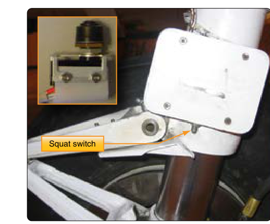
Retractable landing gear dramatically reduces aerodynamic drag and improves aircraft performance, but it introduces a problem that fixed-gear aircraft never face: what keeps the gear from collapsing at the worst possible moment? The answer is a pair of mechanical locking systems — the uplock, which secures the gear in the retracted position during flight, and the downlock, which locks it in the extended position before touchdown. Understanding how these mechanisms work, why they must be inspected so carefully, and how they interact with the rest of the gear system is fundamental knowledge for any airframe technician.
This article covers the design principles, components, inspection criteria, and common failure modes of mechanical uplocks and downlocks as addressed in FAA airframe maintenance standards. Whether you are preparing for the FAA Airframe Knowledge Test or working on your first retractable-gear aircraft, mastering these concepts is essential for both safety and certification.
Why Locking Mechanisms Are Necessary
Retractable landing gear is actuated by hydraulic, electric, or pneumatic power — or some combination of these. During normal operation, actuation pressure moves the gear into position. But actuating pressure alone cannot be relied upon to keep the gear locked. Hydraulic pressure can bleed off through internal leakage; electrical actuators can lose power; pneumatic systems can lose charge. If nothing mechanically secured the gear, any loss of system pressure or power could allow the gear to drift from its intended position. The consequences range from a gear-up landing to an uncommanded extension that damages the aircraft structure or injures occupants.
Mechanical locks solve this problem by providing a positive, independent means of retention that does not depend on continuous system pressure. They engage automatically as the gear reaches its full travel in either direction, and they must be mechanically released before the gear can move again. This two-step requirement — release the lock, then apply actuation — is a fundamental safety feature built into virtually every retractable gear design.
How Downlocks Work
A downlock (sometimes called an over-center lock or gear-down lock) secures the landing gear in the fully extended, weight-bearing position. The most common design uses a set of mechanical links arranged so that when the gear reaches full extension, the linkage passes through the geometric centerline and moves slightly past it — a condition called over-center. Once over-center, any load applied to the gear (such as the weight of the aircraft on touchdown) actually drives the linkage more deeply into the locked position rather than collapsing it. This is mechanically self-locking: the harder the load, the tighter the lock.
In many designs, a spring-loaded lock link or downlock spring provides the additional force needed to snap the linkage over-center as the gear reaches full extension. This spring ensures positive locking even when actuation pressure is low or the gear moves slowly. The locked position is typically confirmed by a downlock switch or sensor that illuminates the green gear-down indicator light in the cockpit. From a maintenance perspective, the spring condition, link geometry, and switch alignment are all critical inspection items.
Some aircraft use a latch-type downlock instead of an over-center arrangement. In these designs, a spring-loaded hook or pawl engages a pin or roller as the gear reaches full extension, physically capturing the gear in the down position. The latch is released by a hydraulic cylinder or electric solenoid when retraction is commanded. Latch-type designs are common on nose gear assemblies where the geometry makes a simple over-center arrangement impractical.
How Uplocks Work
An uplock (also called a gear-up lock or retracted-position lock) serves the opposite function: it holds the gear firmly in the wheel well during flight, preventing aerodynamic forces, vibration, or gravity from causing inadvertent extension. In the retracted position, the gear is typically exposed to significant airstream loads that tend to push it downward and aft. Without a positive mechanical uplock, these forces could gradually work the gear out of its retracted position.
The most common uplock design is a hook-and-roller arrangement. As the gear reaches its fully retracted position, a spring-loaded hook in the wheel well engages a roller or pin attached to the gear structure. The hook is geometrically arranged so that aerodynamic and gravitational loads drive it into engagement rather than out of it. Releasing the uplock is the first step in any gear-extension sequence — the hydraulic, electric, or emergency extension system must first disengage the hook before the gear can move.
On many aircraft, the uplock hook is released by a dedicated uplock cylinder (sometimes called an unlock cylinder), which is pressurized at the beginning of the extension cycle, slightly before the main gear actuating cylinder is pressurized. This sequencing is critical: if the main actuator were pressurized first, it would apply a large load against the locked hook, potentially bending the hook or damaging the roller before release. Proper sequencing is typically achieved with sequence valves in the hydraulic system.
Emergency Extension and Lock Considerations
Every retractable-gear aircraft certificated under 14 CFR Part 23 or Part 25 must have an emergency means of extending the landing gear independent of the normal actuation system. Common emergency extension methods include free-fall systems (which use gravity and spring force after the uplock is manually released), hand-pump hydraulic systems, and pneumatic backup systems. In all cases, the emergency system must first release the uplock before the gear can extend and then engage the downlock before the aircraft lands.
During emergency extension, the sequence of events matters enormously. Technicians must understand that releasing the uplock without providing a means to engage the downlock is not a complete solution — gear that free-falls into the down position will only be safe if the downlock engages positively. Maintenance procedures after any emergency extension always include a thorough inspection of both the uplock and downlock mechanisms for evidence of over-stress, bent links, or damaged springs before the aircraft returns to service.
Key Numbers, Tolerances, and Inspection Points
- Over-center geometry: Manufacturer specifications define the exact amount of over-center travel (often measured in fractions of an inch or in degrees) required to achieve a positive downlock. This dimension must be checked and adjusted during rigging.
- Spring condition: Downlock and uplock springs must be inspected for correct free length, compression load, and freedom from corrosion or cracks. A weak spring may fail to drive the linkage fully over-center or fully engage a hook, resulting in an unsafe condition that cockpit indicators may not reveal.
- Roller and hook wear: Uplock hooks and rollers develop wear surfaces that must be measured against wear limits in the Aircraft Maintenance Manual (AMM). Excessive wear changes the geometry and can prevent positive engagement.
- Downlock switch rigging: Position switches must be rigged so they signal the locked condition only when the mechanism is actually over-center, not merely approaching it. Switch adjustment is a critical safety step after any gear rigging.
- Lubrication: Pivot points, rollers, and sliding surfaces must be lubricated per the AMM schedule. Dry pivots can cause sluggish lock engagement, especially in cold-weather operations when grease thickens.
- Safetying hardware: All cotter pins, castellated nuts, and safety wire on locking mechanisms must be installed correctly. Any missing or incorrect safety hardware is an immediate airworthiness concern.
Common Failure Modes
Technicians encounter several recurring failure patterns in landing gear locking systems. Improper rigging is the most frequent: if the over-center geometry is set incorrectly, the downlock may appear engaged to the position switch while actually being just short of center — a condition where even a moderate side load can unlock the gear. Always verify over-center travel dimensionally, not just by indicator light.
Worn or corroded uplock hooks that fail to fully capture the roller are another serious hazard. The gear may appear retracted and locked but can extend in turbulence or under sustained aerodynamic load. Careful visual inspection during each scheduled maintenance interval is essential. Additionally, a misrigged or failed uplock release cylinder can prevent gear extension entirely, creating an emergency where neither normal nor emergency systems can extend the gear. Understanding the complete release-sequence logic helps technicians diagnose this scenario efficiently.
Common Test Traps
- Confusing the sequence: The uplock must be released before the gear actuator is pressurized for extension. Reversing this sequence in your thinking (or on an exam answer) leads to incorrect troubleshooting conclusions.
- Indicator lights vs. actual lock engagement: A green down-and-locked light confirms switch position, not necessarily true mechanical lock. On the test, remember that switch rigging can be incorrect independently of the mechanical lock geometry.
- Over-center is self-locking, not pressure-dependent: Once the gear linkage is truly over-center, hydraulic or electric pressure is not required to maintain the locked condition. Questions may try to suggest that a hydraulic failure would allow the downlock to disengage — it would not if the mechanism is properly over-center.
- Emergency extension still requires downlock engagement: The FAA tests knowledge that free-fall extension (gravity drop) is only safe if the downlock positively engages. Simply releasing the uplock is not sufficient to confirm a safe condition.
- Spring failure vs. actuator failure: A weak or broken downlock spring may allow the gear to reach the down position without snapping fully over-center, even though the actuator is functioning normally. These two failure modes look different on inspection — do not automatically assume an actuator problem.