When a heavily loaded transport aircraft touches down at high speed, the pilot's instinct to stand on the brakes can easily overpower the tire's grip on the runway. A locked wheel skids rather than rolls, generating far less stopping force than a wheel on the verge of slipping — and it destroys a tire in seconds. Anti-skid brake control systems solve this problem automatically, continuously comparing wheel speed signals against a reference and relieving hydraulic pressure the instant a wheel begins to decelerate faster than physics allow. The result is shorter stopping distances, tire preservation, and directional control that would be impossible with purely manual braking at high energy levels. For the AMT airframe technician, understanding how these systems work, how they are tested, and how failures are diagnosed is essential knowledge for both the written exam and the shop floor.
Anti-skid systems are required equipment on virtually all transport-category airplanes and are common on many turboprop and business jet aircraft. The governing regulations and design standards are found in 14 CFR Part 25 (airworthiness standards for transport-category airplanes), and the systems must be shown to improve stopping performance compared to a locked-wheel condition. The FAA's Aviation Maintenance Handbook — Airframe (FAA-H-8083-31) dedicates specific coverage to hydraulic brake systems, including anti-skid operation, as part of the broader landing gear systems chapter.
How Anti-Skid Systems Work
Every anti-skid system revolves around three functional elements: wheel speed transducers, an electronic control unit (ECU), and anti-skid control valves in the hydraulic brake lines. These three components form a closed feedback loop that operates many times per second.
Wheel Speed Transducers
Each main landing gear wheel is fitted with a wheel speed transducer — typically a variable-frequency AC generator (sometimes called a wheel speed sensor or tachometer generator). As the wheel rotates, the transducer produces an AC voltage whose frequency is directly proportional to wheel rotational speed. The ECU converts this frequency into a computed wheel velocity. On most modern systems, each wheel on a truck-type gear has its own independent transducer, allowing the system to manage individual wheels rather than entire axles.
The Electronic Control Unit
The ECU is the brain of the system. It performs two key calculations continuously. First, it derives a reference velocity — an estimate of the actual ground speed of the aircraft — typically by monitoring the fastest-spinning wheel(s) or by using an inertial reference. Second, it computes the deceleration rate of each individual wheel. When a wheel decelerates faster than a programmed threshold (indicating impending lockup), the ECU sends a command signal to the corresponding anti-skid control valve to reduce hydraulic pressure to that wheel's brake. Once the wheel spins back up toward the reference speed, the ECU commands pressure to be reapplied. This cycle — pressure reduction, wheel recovery, pressure reapplication — repeats at rates that may exceed 10 cycles per second, keeping each wheel operating near its peak slip ratio for maximum braking force.
The optimal braking condition exists at a slip ratio of roughly 10–15 percent — meaning the wheel's peripheral velocity is about 85–90 percent of the aircraft's actual ground speed. At zero slip, the wheel rolls freely with no braking. At 100 percent slip, the wheel is locked and generates only kinetic (sliding) friction, which is significantly lower than the peak rolling friction available just before lockup. Anti-skid control keeps each wheel in that narrow high-friction zone automatically.
Anti-Skid Control Valves
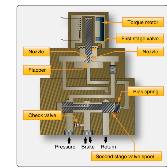
The control valves are electrically operated hydraulic valves inserted in the brake supply lines between the master brake valve (or brake metering valve) and the individual brake assemblies. On command from the ECU, a valve can hold (trap current pressure), decay (dump pressure to return), or build (allow increased pressure) at each wheel independently. Some systems use separate hold and decay solenoids; others use a single proportional valve. The speed and precision of these valves directly determines system response quality.
Special Anti-Skid Modes
Beyond basic skid control, most transport-category systems incorporate several additional protective modes:
- Touchdown protection: Prevents brake application for a brief period (typically one to three seconds) immediately after touchdown, ensuring the wheels are spinning up from initial contact before brake pressure is allowed. This prevents flat-spotting a stationary tire the instant it contacts the runway.
- Locked-wheel protection: If a wheel transducer reads zero speed while the aircraft is moving at significant ground speed — indicating a completely failed or locked wheel — the system automatically dumps all brake pressure to that wheel. This protects against a tire blowout from prolonged skidding.
- Hydroplaning protection (aquaplaning): At very high speeds on wet runways, tires can ride on a film of water and lose contact with the pavement entirely. Some advanced systems incorporate logic that prevents brake application below a computed hydroplaning speed (approximately 9 times the square root of tire pressure in psi, though exact values vary by tire specification), recognizing that braking is ineffective and potentially dangerous during full hydroplaning.
- Fail-safe deactivation: If the ECU detects a system fault — broken transducer wire, valve failure, or internal fault — it typically commands the anti-skid valve to the fully open (maximum pressure) position and illuminates a warning light. The pilot then has full manual brake pressure available, but without anti-skid protection.
Autobrake Integration
Many transport aircraft pair the anti-skid system with an autobrake system. The autobrake uses the aircraft's deceleration rate as its feedback variable, automatically applying brake pressure through the anti-skid valves to achieve a pilot-selected deceleration rate (e.g., LOW, MED, MAX, or RTO — Rejected Takeoff). The anti-skid system remains active underneath the autobrake, preventing any wheel lockup regardless of the autobrake's pressure demand. During an RTO, the autobrake commands maximum pressure instantly, and the anti-skid system modulates individual wheels as needed. The autobrake disengages automatically when the pilot applies manual brake pedal pressure above the autobrake command level, or when the aircraft decelerates to a low speed threshold.
Why Anti-Skid Systems Matter
The safety case for anti-skid systems is compelling. Testing has consistently demonstrated that anti-skid braking reduces stopping distances by 20–40 percent compared to maximum manual braking on dry runways, and by even larger margins on wet or contaminated surfaces where the threshold between grip and slip is extremely narrow. Tire blowouts from skidding represent a serious hazard — a blown main gear tire at high energy can damage the wheel well, fuselage, or fuel systems. Directional control is equally important: asymmetric wheel lockup (one side locked, the other not) produces a strong yawing moment that can lead runway excursions at the speeds involved in transport operations.
For the AMT, these consequences make proper system maintenance critical. A malfunctioning anti-skid system that falsely dumps pressure can leave a crew with severely degraded stopping performance, while one that fails to release pressure can destroy a tire or cause a blown wheel. Neither failure mode is acceptable.
Key Numbers and Rules
- Slip ratio for peak braking: Approximately 10–15% slip between tire surface speed and ground speed provides maximum braking friction coefficient.
- Touchdown protection delay: Typically 1–3 seconds after weight-on-wheels signal before brake pressure is permitted.
- Hydroplaning speed formula: Approximately 9 × √(tire pressure in psi) = hydroplaning speed in knots (e.g., a tire inflated to 200 psi: 9 × √200 ≈ 127 knots).
- System voltage supply: Most ECUs are powered by 28 VDC aircraft bus; loss of power causes fail-safe deactivation.
- Regulatory basis: 14 CFR §25.735 specifies brake system requirements including anti-skid provisions for transport-category aircraft.
- Operational check: Before flight, many systems perform a Built-In Test Equipment (BITE) self-test cycle; the AMT must verify the test completes without fault codes per the Aircraft Maintenance Manual (AMM).
Testing and Troubleshooting
Anti-skid system maintenance requires following the specific Aircraft Maintenance Manual procedures precisely, but the general approach involves several standard checks. The ground functional test uses a test box or the aircraft's own BITE to simulate wheel speed transducer signals; the technician verifies that each anti-skid valve cycles (releases and reapplies pressure) correctly in response to a simulated skid signal. Hydraulic pressure gauges or a brake pressure test fixture confirm the magnitude and timing of pressure changes at each brake assembly.
Transducer continuity and resistance checks confirm the sensor wiring is intact. Wheel speed transducers are tested by spinning the wheel (on jacks) and confirming AC output frequency increases proportionally with speed. Control valves are bench-tested for correct coil resistance and verified to cycle freely without internal leakage exceeding AMM limits. The ECU itself is typically a line-replaceable unit (LRU); if BITE identifies an internal ECU fault, the unit is exchanged and sent to an avionics repair station for deeper troubleshooting.
Common Test Traps
- Confusing locked-wheel protection with touchdown protection: Touchdown protection prevents brake application right after landing; locked-wheel protection releases pressure from a wheel that has already fully stopped rotating during rollout. They are distinct modes with different trigger conditions.
- Assuming anti-skid failure means no brakes: A properly designed fail-safe system defaults to full hydraulic pressure reaching the brakes — the pilot retains manual braking ability, just without anti-skid modulation.
- Misidentifying the transducer output: Wheel speed transducers produce AC voltage with frequency proportional to speed, NOT a simple DC signal. The ECU reads frequency, not voltage magnitude.
- Overlooking hydroplaning protection as an anti-skid function: Some candidates treat hydroplaning protection as a separate unrelated system, when in fact it is implemented as a logic mode within the anti-skid ECU on aircraft that incorporate it.
- Ignoring the autobrake/anti-skid relationship: Anti-skid and autobrake are not the same system. Autobrake selects deceleration rate; anti-skid prevents lockup. The anti-skid system supervises the autobrake's pressure commands at the wheel level.