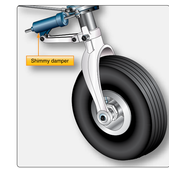
Every time an aircraft rolls out from landing or taxis across a ramp, the nose gear is working hard to keep the airplane pointed in the right direction. Unlike main gear, which are primarily load-bearing structures, the nose gear must simultaneously support the forward section of the aircraft, absorb landing loads, and provide a steerable interface between the cockpit and the pavement. Two interconnected systems make this possible: the nose gear steering system, which gives the pilot directional authority on the ground, and the shimmy damper, which prevents a specific and destructive wheel oscillation from developing into a structural hazard. Understanding both systems — how they are designed, how they fail, and how they are maintained — is essential knowledge for the FAA Airframe Mechanic knowledge test and for safe aircraft maintenance practice.
How Nose Gear Steering Works
The fundamental job of a nose gear steering system is to rotate the nose wheel assembly about its vertical axis (the steering axis) in response to pilot input. On small general aviation aircraft, this is often accomplished through a simple mechanical linkage. Rudder pedal movement is transmitted via cables, pushrods, or a combination of both to a steering collar or horn attached to the nose gear strut. When the pilot pushes the left rudder pedal, the mechanical connection turns the nose wheel to the left, and the aircraft follows. This system is elegant in its simplicity but is inherently limited in the steering angle it can achieve — typically in the range of roughly 10 to 20 degrees in either direction, though the exact figure varies by aircraft design.
Larger transport-category aircraft require far greater nose wheel deflection for tight maneuvering (commonly cited figures range roughly 60–78 degrees depending on the specific aircraft type) and the mechanical forces involved are too great for a simple cable linkage. These aircraft use hydraulic nose gear steering systems. A dedicated steering metering valve, controlled by a tiller (a small wheel or handle at the captain's station) or by rudder pedal input at lower deflection angles, directs hydraulic pressure to one side of a steering actuator attached to the nose gear torque links or steering collar. The actuator rotates the nose wheel to the commanded angle. Position feedback — often a mechanical feedback cam or an electronic position sensor — closes the control loop and stops the actuator when the desired angle is reached. Many designs incorporate dual authority: the rudder pedals command smaller angles (say, 7–10 degrees) during the takeoff roll for fine tracking, while the tiller is required for the large angles needed during slow taxi and ramp maneuvering.
A third category — electro-hydraulic or fly-by-wire steering — is found on modern glass-cockpit transport aircraft. Here, pilot tiller or pedal input is sensed electronically, a steering control unit calculates the appropriate actuator command, and an electro-hydraulic servo valve meters fluid to the steering actuator. The system provides smooth, programmable steering response and can incorporate automatic nose wheel centering commands during gear retraction, preventing the nose wheel from being stowed in an off-center position that could damage the gear bay or wheel well structure.
Torque Links and the Steering Collar
An important structural element closely related to steering is the torque link (sometimes called scissors or torque scissors). Torque links are paired hinged arms that connect the outer cylinder of the nose gear shock strut to the inner (piston) cylinder. They allow the strut to compress and extend freely while preventing the wheel from rotating freely about the strut axis — that is, they transfer steering input from the collar down to the axle and wheel. Without torque links, a steered input at the top of the strut would simply twist the outer cylinder without turning the wheel. Torque link condition, alignment, and lubrication are critical inspection points: worn or loose torque link attach bolts are a primary contributor to shimmy.
What is Nose Gear Shimmy?
Shimmy is a rapid, self-sustaining oscillation of the nose wheel assembly from side to side about the steering axis. It is not just vibration — it is a resonant phenomenon. When a wheel rolls along a surface, small lateral disturbances (pavement imperfections, tire flat spots, slight imbalance) introduce a side force on the tire contact patch. This force creates a restoring moment that swings the wheel back, but because of the inertia of the wheel and strut assembly, the wheel overshoots center. Combined with the caster geometry of the nose gear, this can establish a feedback loop in which each oscillation reinforces the next. Shimmy frequency varies considerably depending on aircraft type, gear design, tire condition, and damper effectiveness — it is not a fixed, universally specified value — but it is typically fast enough to be felt as a violent buzz or shake through the airframe, the instrument panel, and the pilot's rudder pedals.
Shimmy is not merely uncomfortable. At high frequency, the alternating loads imposed on the nose gear attach fittings, torque links, and wheel-to-axle interfaces can quickly exceed design limits and cause fatigue cracking or outright failure. There are well-documented accidents in which uncontrolled shimmy led to nose gear collapse during landing rollout.
The Shimmy Damper
A shimmy damper is a hydraulic device designed to absorb the energy of these oscillations before they can build to dangerous amplitude. In construction, most shimmy dampers resemble a small hydraulic cylinder: a piston moves inside a fluid-filled cylinder, and small orifices or calibrated valving restrict the flow of fluid from one side of the piston to the other. This fluid resistance (viscous damping) opposes rapid motion of the piston while having relatively little effect on the slow, deliberate movements of normal steering — the key characteristic that distinguishes damping from simply locking the steering system.
Shimmy dampers are mounted in two primary configurations:
- Linear (axial) dampers: The damper cylinder attaches to the airframe or strut outer cylinder at one end and to a steering arm or torque link at the other. As the wheel oscillates, the steering arm moves the piston in and out, and the fluid resistance absorbs the oscillation energy.
- Rotary dampers: Instead of linear piston motion, a vane or gear mechanism converts the rotary motion of the nose gear about its steering axis into fluid shear resistance. These are more compact and are common on larger aircraft where available installation space is limited.
Shimmy dampers are self-contained with a sealed fluid reservoir, but most include an inspection port or fluid level check provision. Low fluid level directly degrades damping effectiveness. The fluid used is typically hydraulic fluid compatible with the aircraft's hydraulic system or a specific specification called out in the aircraft maintenance manual — never substitute fluids without verifying compatibility.
Why These Systems Matter for Safety and Maintenance
From a maintenance perspective, shimmy damper serviceability must be checked regularly. Signs of a failing or failed shimmy damper include visible external leakage (wet streaks of hydraulic fluid on the damper body), a reported history of shimmy during rollout, or physical looseness when the nose wheel is manually rocked side-to-side with the aircraft on jacks. Worn torque link bushings produce similar symptoms, so the entire nose gear assembly must be evaluated together — replacing a failed shimmy damper will not cure shimmy caused by excessive torque link play.
Tire condition matters as well. A tire with a flat spot (from a skid), uneven wear, or incorrect inflation introduces an uneven contact patch force that can initiate shimmy even with a serviceable damper. The maintenance technician should always check tire condition and inflation as part of any shimmy investigation.
Key Numbers and Rules
- Mechanical steering systems on GA aircraft typically provide roughly 10 to 20 degrees of nose wheel deflection from center, though the exact figure varies by specific aircraft design.
- Hydraulic tiller-controlled systems on transport aircraft may command large angles for tight ramp maneuvering, with commonly cited figures ranging roughly 60–78 degrees depending on aircraft type.
- Shimmy frequency varies by aircraft type and gear design and is not a fixed universal value — it is generally fast enough to be felt as a distinct, rapid oscillation distinguishable from slower structural vibration.
- Shimmy damper fluid level must be checked per the aircraft maintenance manual interval — low fluid is the most common cause of recurrent shimmy after other causes are ruled out.
- Torque link bolt and bushing wear limits are specified in the aircraft maintenance manual; exceeding them requires immediate replacement before return to service.
- Nose wheel centering must be confirmed before gear retraction; many aircraft have mechanical centering cams or hydraulic centering circuits to accomplish this automatically.
Common Test Traps
- Confusing shimmy with simple vibration: Shimmy is a specific resonant oscillation about the steering axis, not general airframe vibration. The FAA tests whether you understand its mechanism, not just its name.
- Overlooking torque links as a shimmy cause: Worn or improperly lubricated torque link bushings are just as capable of causing shimmy as a failed shimmy damper. Test questions may present both as answer choices; the correct diagnostic approach evaluates the entire system.
- Assuming any hydraulic fluid will work in a shimmy damper: Fluid specifications are aircraft-specific. Using an incompatible fluid can damage seals and cause rapid damper failure.
- Thinking the rudder pedals always command full steering angle: On most larger aircraft, rudder pedals command only a limited steering angle (for runway tracking), while the tiller commands full deflection. Mixing these up on a test question will cost points.
- Forgetting nose wheel centering before retraction: A nose wheel stowed in an off-center position can jam the gear bay or damage wheel well structure. Centering systems — whether mechanical cam, hydraulic, or electronic — are a required functional check during gear rigging.