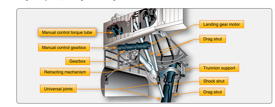
Landing gear actuation is one of the most safety-critical functions on any retractable-gear aircraft. While hydraulic systems dominate large transport-category airplanes, a significant number of light and medium aircraft rely on electric motor-driven landing gear systems to raise and lower the gear. Understanding how these systems work — from the motor through the transmission to the gear itself — is essential knowledge for the Airframe AMT. It also helps explain why these systems behave the way they do in both normal operation and emergency situations.
Electric actuation systems replace the hydraulic cylinder with a reversible direct-current (DC) electric motor that drives a mechanical linkage. The simplicity of running wires instead of hydraulic lines makes this approach attractive for smaller airplanes. The Cessna 210 is a well-known example of an electrically-driven retractable gear system; gear actuation methods vary by manufacturer and model, and mechanics should always consult the specific aircraft's maintenance manual rather than assume a common design across families. The FAA's Aviation Maintenance Handbook — Airframe (FAA-H-8083-31) addresses landing gear systems in depth and forms the primary reference for AMT knowledge on this topic.
Core Components of an Electric Gear System
Every electric landing gear system shares a common set of building blocks, though the exact arrangement varies by manufacturer.
- Reversible DC motor: The prime mover. Current direction through the armature determines whether the motor turns in the extension or retraction direction. Most aircraft use a 28-volt DC motor, though some older designs use 14-volt systems. Motor size is carefully matched to the mechanical load and duty cycle — the motor is typically designed for short, intermittent operation, not continuous running.
- Gear reduction unit: The motor spins very fast at low torque. A worm-gear or spur-gear reduction box converts high-speed, low-torque rotation into the low-speed, high-torque output needed to drive the gear actuator. The reduction ratio may be 100:1 or higher.
- Actuating mechanism: The gearbox output connects to either a jackscrew (linear actuator), a torque tube, or a bellcrank-and-pushrod arrangement that translates rotation into the travel needed to swing the gear into position. A jackscrew is a common choice for these systems; whether a given jackscrew design is self-locking depends on the thread's lead angle and friction characteristics, so not every jackscrew installation resists back-driving to the same degree — the AMT must consult the specific aircraft's design data rather than assume self-locking behavior.
- Limit switches: Microswitches at the full-up and full-down positions interrupt motor current automatically when the gear reaches its endpoint. This prevents the motor from running against a mechanical stop, which would overheat and burn out the windings. Properly rigged limit switches are crucial for system longevity and safety.
- Circuit breaker or fuse: Protects the wiring and motor from overcurrent. The breaker is typically sized slightly above the normal operating current draw. A breaker that trips repeatedly is a sign of a mechanical binding problem, not a reason to simply reset and continue.
- Gear selector switch and relay (contactor) assembly: The cockpit switch does not carry the full motor current. Instead, it energizes control relays (contactors) that in turn connect battery power directly to the motor in the correct polarity. This protects cockpit wiring from high-current loads.
- Position indicators: Usually three green lights (one per gear) confirm down-and-locked. An unsafe or in-transit condition is shown by a red or amber light, or by the green lights extinguishing. Some designs use a single barber-pole or striped indicator for an unsafe condition.
Operational Sequence — What Happens When You Select Gear Up
Walking through the actuation sequence step by step clarifies how the components interact. When the pilot moves the gear selector to the UP position, the selector switch closes a circuit that energizes the UP contactor (relay). The contactor closes and applies full bus voltage across the motor terminals in the retraction polarity. The motor begins to spin, driving the gearbox, which rotates the jackscrew or torque tube. The mechanical linkage pulls each gear leg upward and inward into its bay.
As the gear approaches the fully retracted position, a cam or actuating arm on the linkage contacts the up-limit microswitch. The switch opens, breaking the motor circuit and stopping the motor. Gear doors, if present, may be operated by separate motors or by mechanical connections to the main gear linkage. With the gear fully up, on designs using a self-locking jackscrew or worm-gear arrangement, the thread geometry can help keep the gear in place without relying on motor torque or a holding brake — but this depends on the specific design, and the AMT should verify the locking characteristics of the actual installation rather than assume it applies universally.
Selecting gear DOWN reverses the process. The DOWN contactor energizes, reversing motor polarity, and the jackscrew extends the gear outward and downward. When the gear reaches full extension and the downlocks engage (usually a spring-loaded overcenter mechanism or a positive locking pin), the down-limit switch opens and stops the motor. The green position-indicator lights illuminate, confirming each gear is down and locked.
Safety and Interlock Features
Electric gear systems incorporate several interlocks to prevent inadvertent or dangerous actuation.
- Squat switch (weight-on-wheels switch): A microswitch on the main gear oleo strut or landing gear mechanism that detects when the aircraft is on the ground. On the ground, the squat switch opens the gear-up circuit, preventing retraction while taxiing. This is the most important single safety interlock in the system.
- Airspeed interlock: A small number of specific aircraft designs incorporate an airspeed-sensing switch as an additional layer of protection against inadvertent gear retraction; this feature is not common across light electric-gear singles generally, and its presence or absence must be verified against the specific aircraft's system description.
- Gear warning horn: Triggered by a combination of throttle position (low-power setting) and gear position (not down-and-locked). The warning horn alerts the crew of a possible gear-up landing.
- Overcurrent protection: If the gear jams or a mechanical binding occurs, motor current rises dramatically. The circuit breaker trips before the motor windings can overheat and fail.
Emergency Extension
All retractable-gear aircraft must provide an alternate means of gear extension independent of the normal system. On electric systems, the emergency method typically involves one of the following approaches:
- Manual crank or handcrank: A removable crank handle inserted into a gear-box fitting allows the pilot to hand-crank the jackscrew, driving the gear down by muscle power. The electric motor circuit is usually opened first (by pulling the gear circuit breaker) to prevent the motor from opposing the manual effort.
- Free-fall with mechanical release: Some designs incorporate a release handle or knob that disengages the uplock mechanism, allowing gravity and aerodynamic drag to swing the gear into the down-and-locked position. The pilot may need to slow to a specific speed or perform gentle maneuvering to ensure the gear swings fully down.
- Backup electrical source: A small number of aircraft route the gear motor circuit to a separate battery or emergency bus, allowing gear extension even if the main bus has failed.
Regardless of method, the emergency procedure always ends with verifying green indicator lights and, where applicable, checking a mechanical downlock indicator (a pin protruding through the wing skin or a sight window) before landing.
Inspection and Maintenance Considerations
The AMT must pay close attention to several areas during routine inspection of an electric gear system. The motor brushes wear over time and must be checked for length; worn brushes cause increased resistance, voltage drop, and sluggish operation. Wiring and connector pins in the gear bay are exposed to moisture, vibration, and temperature extremes — corrosion at these connections is a common cause of intermittent faults. The jackscrew or torque tube must be inspected for wear, proper lubrication per the manufacturer's maintenance manual, and absence of cracks. Limit switch rigging must be verified so the switches open at the correct endpoint; a switch that opens too early can leave the gear not fully down-and-locked, while one that opens too late allows the motor to stall against a hard stop. All downlock and uplock mechanisms must be checked for proper overcenter travel and spring tension.
Key Numbers and Rules
- Most light-aircraft electric gear systems operate on 28-volt DC; older designs may use 14-volt systems.
- Gear reduction ratios between the motor and actuator are typically 100:1 or greater to provide necessary torque.
- The squat switch prevents gear retraction on the ground — it is a safety-of-flight component and must be rigged exactly per manufacturer specifications.
- Motor duty cycle is typically intermittent; repeated cycles without pause can overheat the motor — always follow manufacturer guidance on maximum cycles per period.
- A tripping circuit breaker during gear operation signals mechanical binding, not an electrical nuisance — investigate before resetting.
- Emergency extension procedures are aircraft-specific and are detailed in the applicable POH/AFM and maintenance manual; pilots and mechanics must consult and know the exact procedure published for each make and model rather than rely on general assumptions.
Common Test Traps
- Limit switches versus position indicators: Limit switches stop the motor; position indicators (lights) confirm gear position. These are separate circuits. A green light confirms the downlock, but the limit switch is what stops the motor at full travel — confusing the two is a common knowledge-test error.
- Self-locking worm gear: Students often assume every jackscrew or worm-gear actuator is automatically self-locking. In fact, whether the mechanism holds position without motor power depends on the thread's lead angle and friction — some designs are self-locking, others are not, so the AMT must verify the specific system's design rather than generalize.
- Squat switch purpose: The squat switch prevents inadvertent retraction on the ground. Some students incorrectly believe it is part of the warning horn circuit — the horn uses throttle and gear position inputs, not the squat switch directly (though designs vary).
- Circuit breaker behavior: A circuit breaker that pops during gear operation should never be routinely reset and ignored. It is a mechanical problem indicator. Repeatedly resetting it risks motor burnout and potential gear system failure.
- Emergency crank direction: On handcrank systems, the pilot must disengage the motor circuit first. Cranking against a powered motor (with the breaker in) creates opposing torque and can damage the gearbox or injure the user — a detail often tested in maintenance scenarios.