When an airline, cargo carrier, or Part 135 charter operator dispatches a transport-category aircraft, the flight crew and dispatcher share a legal and safety obligation: the airplane must be able to climb away from every runway and clear every obstacle along the departure path—even if the most critical engine fails at the worst possible moment. Title 14 CFR Part 25 (Airworthiness Standards: Transport Category Airplanes) codifies the minimum climb gradients that a certificated transport-category airplane must achieve during each phase of departure. Those gradient minimums translate directly into maximum allowable takeoff weights, drive operator performance engineering, and appear on the Airline Transport Pilot knowledge test in nearly every administration. This article walks through the what, the how, and the why of every segment—with the numbers, the edge cases, and the operational implications that make the difference between a passing grade and a dangerously shallow understanding.
The Takeoff Flight Path: An Overview
Part 25 divides the takeoff flight path into four segments, each characterized by a distinct aircraft configuration, power setting, speed, and—in most cases—a minimum required net climb gradient. The path begins at the point where the aircraft lifts off (the 35-foot screen height above the runway surface used as the reference point for obstacle accountability) and continues until the airplane reaches a safe maneuvering altitude, traditionally defined as 1,500 feet above the runway elevation with all obstacle-clearance requirements satisfied. One engine is assumed inoperative throughout all four segments; that single assumption is what makes the requirements so demanding and so safety-significant.
First Segment: Gear Retraction
The first segment begins at liftoff (the 35-foot screen height) and ends when the landing gear is fully retracted. The engines operate at takeoff (maximum) thrust, flaps remain in the takeoff position, and the airplane climbs at or above V2. The single regulatory requirement for this segment is that the net climb gradient must be positive—the airplane must not descend. No specific numerical percentage is mandated beyond zero. This may seem lenient, but the extended, drag-producing landing gear places an enormous aerodynamic penalty on the airplane. With one engine inoperative, even maintaining altitude while the gear tracks upward is a meaningful accomplishment for some heavily loaded aircraft. The first segment is therefore kept as short as mechanically possible; operators use accelerated gear retraction schedules to minimize time in this vulnerable configuration.
Second Segment: The Critical Climb
The second segment is universally recognized as the most performance-critical phase of the departure. It begins the moment the landing gear is fully retracted and ends at a minimum altitude of 400 feet above the runway elevation. Configuration is clean of gear drag; takeoff flaps remain extended; engines remain at full takeoff thrust; and the airplane climbs at exactly V2—the takeoff safety speed that provides adequate stall margin with one engine out. Part 25 mandates the following minimum net climb gradients during the second segment:
- Two-engine aircraft: 2.4%
- Three-engine aircraft: 2.7%
- Four-engine aircraft: 3.0%
Notice the pattern: each additional engine adds roughly 0.3 percentage points to the requirement. This is not a paradox—larger, multi-engine aircraft carry more passengers and operate into more complex environments, so regulators impose a stricter standard as fleet size and capacity grow. Because the airplane is heavy, slow, and operating on reduced thrust, the second segment is almost always the limiting constraint when calculating maximum allowable takeoff weight. Performance engineers call this the "second-segment limit," and at hot, high, or contaminated-runway airports it can force a meaningful weight reduction before dispatch.
One critical nuance: the 400-foot floor is a minimum, not a fixed endpoint. If terrain or man-made obstacles penetrate the obstacle identification surface above 400 feet, the second segment must be extended—engines held at takeoff thrust, speed held at V2, flaps kept in the takeoff position—until the obstruction is cleared. Takeoff thrust is time-limited (typically five minutes for most certificated powerplants), so extended second-segment climbs add another layer of planning complexity.
Third Segment: The Acceleration Segment
The third segment spans the altitude band between approximately 400 feet and 1,000 feet above the runway elevation. During this phase the aircraft levels off (or nearly so), maintains takeoff thrust, and accelerates from V2 to the flap-retraction speed. As speed builds, flaps retract on schedule until the wing is in the clean configuration. This is sometimes called the acceleration segment for exactly that reason.
Part 25 specifies no minimum climb gradient for the third segment—the aircraft is permitted to fly nearly level while it accelerates. However, obstacle clearance accountability does not disappear. The aircraft's flight path must still clear all obstacles within the obstacle identification surfaces by the required margins; operators must verify that the near-level acceleration profile does not place the airplane closer to an obstacle than the rules allow. Additionally, flap retraction must be complete before the fourth segment begins, and the entire retraction schedule must be accomplished within the takeoff thrust time limit.
Fourth (Final) Segment: En Route Configuration
The fourth segment begins once the flaps are fully retracted and the aircraft has accelerated to en route climb speed. At this point, the engines are reduced from takeoff thrust to maximum continuous thrust—the highest power setting permitted for unrestricted duration. The airplane climbs in a clean configuration at en route climb speed until reaching 1,500 feet above the runway elevation (or until all obstacle accountability is satisfied). Part 25 minimum net climb gradients for the fourth segment are:
- Two-engine aircraft: 1.2%
- Three-engine aircraft: 1.5%
- Four-engine aircraft: 1.7%
The lower values compared to the second segment reflect the cleaner configuration, higher speed, and the longer time available for obstacle clearance. Nevertheless, at a degraded-engine thrust setting, even 1.2% can be a meaningful challenge for a heavily loaded twin at a high-elevation airport on a hot day.
Gross vs. Net Gradient: A Tested Distinction
Part 25 performance is calculated using the net flight path, not the gross (actual demonstrated) flight path. The net gradient is the gross gradient reduced by a conservatism factor—approximately 0.8% for two-engine aircraft, 0.9% for three-engine, and 1.0% for four-engine aircraft. This margin accounts for real-world variations in piloting technique, atmospheric conditions, and powerplant deterioration. When Part 25 states "2.4% for twins," it means the net gradient must reach 2.4%—the actual airplane must therefore be capable of achieving roughly 3.2% gross to produce the required net. The distinction between gross and net is a favorite knowledge-test trap.
Operational Impact: Weight, Weather, and Procedure
These gradient requirements have direct, daily operational consequences. Operators compute a maximum performance-limited takeoff weight for every departure based on temperature, pressure altitude, wind, runway length, and the obstacle environment. When the second-segment gradient requirement cannot be met at the desired weight, options include: reducing fuel load or payload, selecting a different runway or departure procedure, waiting for cooler temperatures, or using an engine-out escape route approved under the operator's performance engineering program.
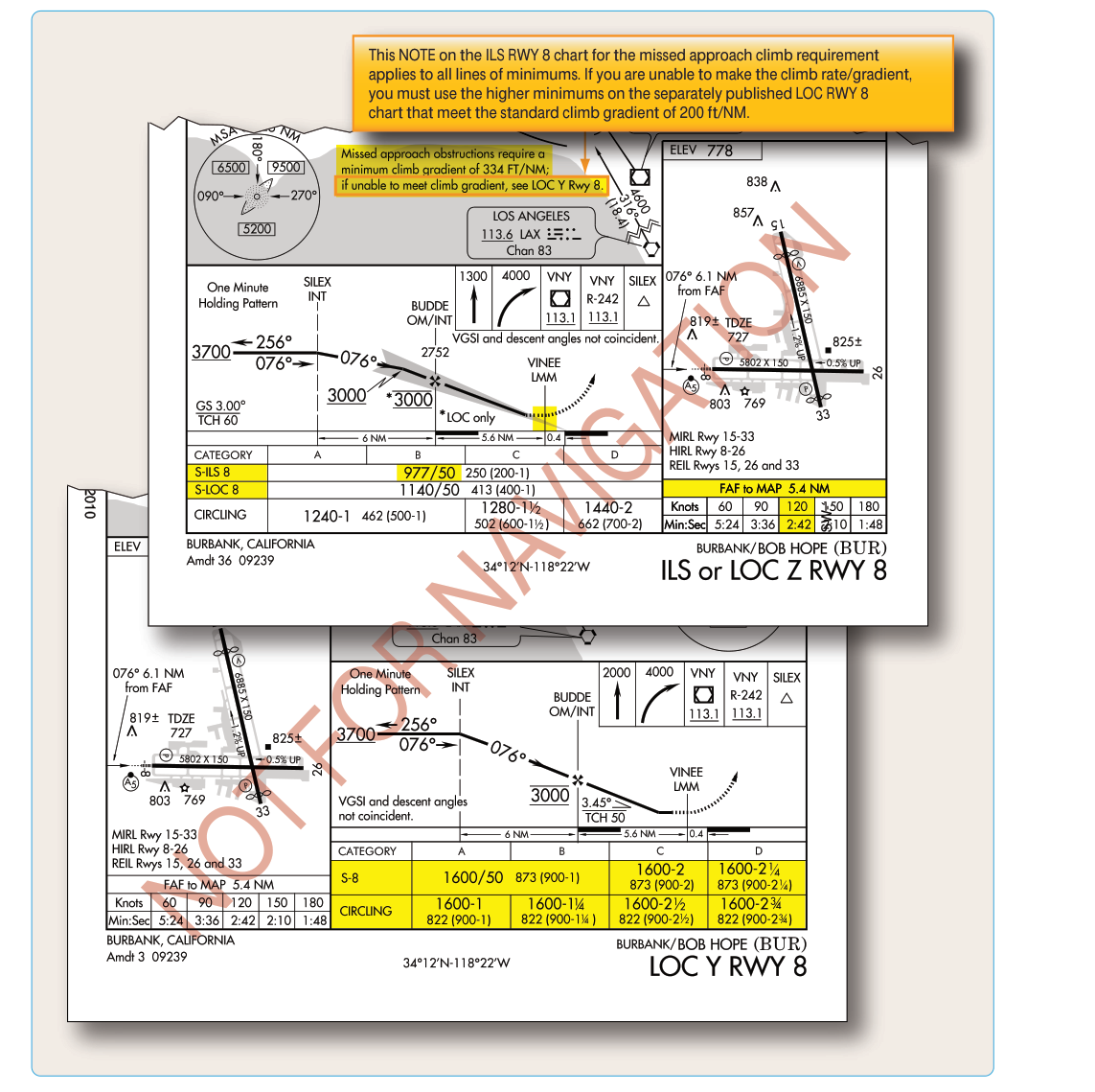
Published Obstacle Departure Procedures (ODPs) and some Standard Instrument Departures (SIDs) specify required climb gradients (expressed in feet per nautical mile, e.g., "500 ft/NM"). Crews must verify their aircraft can meet the published gradient at the planned weight; if not, an alternate departure must be selected or the weight reduced. Converting feet-per-nautical-mile to a percentage is straightforward: 200 ft/NM ≈ 3.3%, because one nautical mile equals approximately 6,076 feet.
Key Numbers and Rules at a Glance
- First segment: gear retracting, positive gradient only (no descent).
- Second segment: gear up, takeoff flaps, V2, takeoff thrust — 2.4% / 2.7% / 3.0% (2 / 3 / 4 engines).
- Third segment: near-level acceleration, flap retraction — no minimum gradient specified.
- Fourth segment: clean, en route speed, max continuous thrust — 1.2% / 1.5% / 1.7% (2 / 3 / 4 engines).
- Net gradient = gross gradient minus ~0.8–1.0% engineering margin.
- Second segment ends at 400 ft AGL minimum; may be extended for obstacles.
- Fourth segment ends at 1,500 ft AGL or when obstacle accountability is satisfied.
Common Test Traps
- Positive gradient only in first segment: Candidates sometimes cite a specific percentage for the first segment. Part 25 requires only a positive (non-zero) gradient—no numerical minimum beyond zero.
- Third segment has no gradient requirement: Every segment-count question on the knowledge test implies all four have mandatory gradient values. Only the third segment lacks a minimum—a fact worth memorizing explicitly.
- 400 feet is a floor, not a ceiling: Many candidates assume the second segment always ends exactly at 400 feet AGL. In obstacle-rich environments it can and must continue higher.
- Mixing up second vs. fourth segment values: Distractors often substitute 1.2% into a second-segment question or 2.4% into a fourth-segment question. Anchor the values by segment, not just by engine count.
- Confusing net and gross gradient: Any question asking what Part 25 "requires" refers to the net gradient. The actual performance must exceed this by the engineering margin.
- Engine count logic: More engines = higher required gradient percentage, not lower. The regulatory philosophy is that larger aircraft must be held to a more stringent standard.