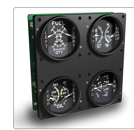
Every time a pilot or mechanic glances at an engine instrument, they are reading a carefully engineered visual language. The colored arcs, lines, and radial marks on tachometers, manifold pressure gauges, oil temperature and pressure gauges, cylinder head temperature gauges, and other powerplant instruments are not decorative — they are federally mandated safety indicators that communicate normal operating ranges, caution zones, and absolute limits without requiring the reader to memorize a single number. Understanding this color-coding system is essential for any Aviation Maintenance Technician (AMT) who inspects, repairs, installs, or approves instruments for return to service, and it is a heavily tested subject area on the FAA AMT Powerplant knowledge exam.
The regulatory authority for instrument markings flows from 14 CFR Part 23 (for normal, utility, acrobatic, and commuter category airplanes) and the applicable aircraft Type Certificate Data Sheets (TCDS), with the practical guidance codified in the FAA's Airframe and Powerplant handbooks. The Aircraft Maintenance Manual (AMM) for each specific aircraft defines the exact numerical values that correspond to each color band, but the color system itself is standardized across certificated aircraft so that any trained technician or pilot can interpret any panel.
The Standard Color-Coding System
FAA standards define five primary colors used on engine instrument faces. Each color carries a specific, universally understood meaning. Learning what each color represents — and what physical form it takes on the instrument face — is the foundation of this topic.
- Red Radial Line (Red Line): A red radial line marks a maximum or minimum limit that must never be exceeded. It is the most critical marking on any instrument. On a tachometer, a red line at the top of the scale marks maximum allowable RPM. On an oil pressure gauge, a red line at the low end marks the minimum pressure below which operation is prohibited. Operation beyond a red line is outside the aircraft's type certificate limits and may cause immediate structural or mechanical damage. Red lines are single radial lines — not arcs — placed precisely at the limiting value.
- Green Arc: The green arc indicates the normal operating range. The instrument should spend the vast majority of its operating time with the pointer inside the green arc. For example, on an oil pressure gauge the green arc spans from normal idle pressure up to the normal cruise pressure. The green arc communicates "all is well" at a glance. It is a continuous arc covering the span from the lower limit of normal operation to the upper limit of normal operation.
- Yellow Arc: The yellow arc indicates a caution range — a region where operation is permissible for limited time or under specific conditions, but where the pilot or technician should be alert to a developing problem. On many engine instruments the yellow arc appears between the top of the green arc and the red line, signaling that the engine is being pushed toward its limit. Some instruments also have a yellow arc at the low end, below the green arc. Yellow means "proceed with caution" and typically warrants immediate attention and corrective action.
- Red Arc: A red arc (as opposed to a red radial line) marks a range of operation that is prohibited. The most common example is a propeller or engine RPM range that produces harmful resonance or vibration — the so-called "avoid" or "restricted" RPM band. The engine must be operated through this range as quickly as possible and must never be held steady within it. On a tachometer, you may see a red arc somewhere in the mid-range, indicating a resonance band forbidden for continuous operation.
- White Arc: On engine instruments, a white arc is less common than on airspeed indicators, but when present it typically indicates a specific operational range authorized under certain conditions, such as a power-off or certain mixture setting range. The specific meaning depends on the instrument type and is defined in the aircraft's flight manual and TCDS.
Instrument-Specific Applications
Tachometer
The tachometer is one of the most marking-intensive engine instruments. It displays engine RPM for reciprocating engines (or propeller RPM for some installations). The green arc spans the normal continuous operating range. A yellow arc, if present, appears just below the red line at maximum RPM, indicating a range permissible for short-duration operation only. A red radial line sits at maximum allowable RPM. Critically, some tachometers include a red arc in the mid-range indicating a propeller or engine resonance band — RPM values where vibration becomes structurally harmful and continuous operation is prohibited. The pilot or technician must recognize this red arc is not a high-limit marker but a forbidden operating zone.
Manifold Pressure Gauge
For turbocharged or supercharged engines, the manifold pressure gauge is marked with a green arc for the normal operating range and a red radial line at maximum allowable manifold pressure. A yellow arc may appear just below the red line as a caution zone. The absence of a yellow arc on some aircraft does not mean the caution zone does not exist — it means the transition from green directly to red, and the pilot must respect the red line absolutely.
Oil Temperature Gauge
The oil temperature gauge carries a green arc for the normal operating temperature range, a yellow arc for the caution range (which may appear both at the high end and, in some designs, at the low end to indicate that the oil has not yet reached operating temperature), and a red radial line at the maximum allowable oil temperature. Operating with the pointer in the low-end yellow arc at engine start is normal and expected; the pilot should avoid high-power operation until the oil temperature pointer reaches the green arc.
Oil Pressure Gauge
Oil pressure markings include a green arc for normal operating pressure, a yellow arc at the low end (caution — pressure is below normal but above the absolute minimum), a red radial line at minimum allowable pressure, and often a red radial line at maximum allowable pressure as well. Loss of oil pressure is one of the most time-critical engine emergencies, making the low red line on this gauge among the most important markings on the entire panel.
Cylinder Head Temperature (CHT) Gauge
The CHT gauge is marked with a green arc for the normal range, a yellow caution arc at the high end, and a red line at maximum CHT. Exceeding the CHT red line risks detonation, preignition, and permanent engine damage. Technicians verifying CHT instrument markings must confirm that the red line value matches the engine manufacturer's limits as published in the TCDS and engine Type Certificate.
Why This System Matters for AMTs
An AMT is responsible for verifying that instrument markings are correct, legible, and in accordance with the aircraft's current TCDS and applicable Airworthiness Directives (ADs) every time an instrument is installed or an annual/progressive inspection is completed. If an instrument's markings are faded, peeling, obscured by a cracked glass cover, or simply wrong relative to the TCDS values, the instrument is unairworthy and the aircraft cannot be returned to service. Marking errors are an insidious hazard: a red line placed 50 RPM too high, for example, could allow a pilot to unknowingly overstress the engine. The AMT must cross-reference each marking value against the aircraft's TCDS, the Pilot's Operating Handbook (POH) or Airplane Flight Manual (AFM), and the engine manufacturer's data.
Additionally, when instruments are repaired or replaced, the replacement instrument must be re-marked to match the specific aircraft's approved limits — not simply accepted with generic factory markings, which may not correspond to the installed engine's rating or the airframe's operating envelope.
Key Numbers and Rules
- Red radial lines = never-exceed or never-go-below limits; single lines, not arcs.
- Green arcs = normal continuous operating range.
- Yellow arcs = caution range; limited or conditional operation only.
- Red arcs = prohibited operating range (commonly resonance bands on tachometers).
- All markings must be on the instrument face or cover glass; if on the cover glass, they must be re-applied if the glass is replaced.
- Markings must match the aircraft's TCDS and approved AFM/POH — not generic instrument factory defaults.
- A cracked, fogged, or otherwise unreadable instrument face or glass renders the instrument unairworthy.
- 14 CFR Part 23 and the applicable TCDS govern which instruments are required and what limits apply.
Common Test Traps
- Red line vs. red arc confusion: The FAA exam frequently tests whether students know that a red radial line marks a limit value (a single point), while a red arc marks a range of prohibited operation. Confusing the two leads to wrong answers about tachometer markings.
- Yellow arc placement: Students often assume the yellow arc only appears at the high end of a scale. Many engine instruments (especially oil temperature and oil pressure gauges) also have a yellow arc at the low end, indicating the engine has not yet reached safe operating temperature or pressure. Both ends matter.
- Who sets the values: The FAA exam may ask what document governs the specific numerical values on instrument markings. The answer is the aircraft's TCDS (and AFM/POH), not the instrument manufacturer's generic data sheet.
- Marking location: If instrument markings are painted on the cover glass rather than the instrument face, they must be re-applied whenever the glass is replaced. The FAA tests this nuance — failing to re-mark after glass replacement is a maintenance error.
- Unairworthy instruments: An instrument with faded, missing, or incorrect markings makes the aircraft unairworthy, even if the underlying instrument mechanism is functioning perfectly. Many students underestimate how strictly the FAA treats marking integrity.