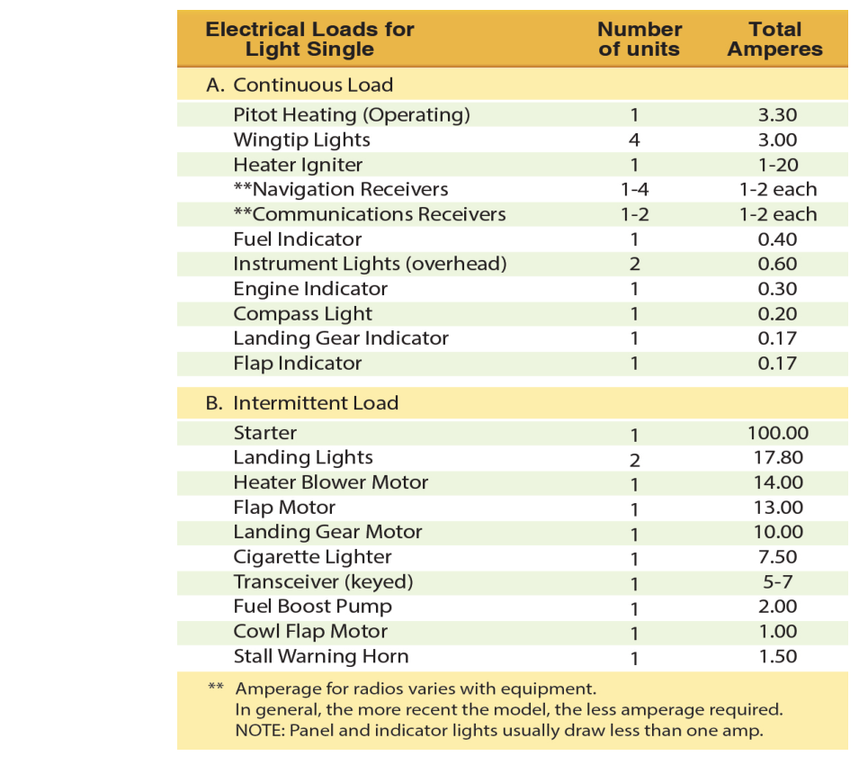
Modern light aircraft depend on electricity for far more than most student pilots initially appreciate. From the attitude indicator (if electrically driven) to the transponder, navigation radios, fuel quantity gauges, and landing light, nearly every system aboard draws current from the same limited electrical bus. When the alternator or generator fails — or when a serious fault develops — the aircraft is suddenly running on battery power alone, and that battery has a very finite life. Understanding how the electrical system works, how to recognize a failure, and how to methodically reduce the electrical load are skills that can be the difference between a safe landing and a cockpit that goes dark at the worst possible moment.
This article covers the architecture of the typical light-aircraft electrical system, the failure modes you are most likely to encounter, and the discipline of load shedding — strategically turning off non-essential equipment to extend battery life for the equipment you truly cannot do without.
How the Electrical System Works
Most single-engine training aircraft use a direct-current (DC) electrical system operating at 14 volts or 28 volts. The system has three main components working together: the battery, the alternator (or generator on older aircraft), and the bus bar (or electrical bus), which is the distribution point from which circuits branch out to individual systems.
Under normal conditions, the alternator supplies all the electrical current the aircraft needs and simultaneously keeps the battery charged. The alternator is driven by the engine and produces alternating current internally, which a voltage regulator converts to regulated DC before it reaches the bus. As long as the alternator is producing its rated output and the load does not exceed that output, the battery stays at or near full charge and contributes nothing to normal operations — it is simply a reserve.
The battery serves two primary purposes: it provides the burst of power needed to start the engine, and it acts as a backup power source if the alternator fails. A typical 12-amp-hour battery in a light trainer may provide enough current to run essential avionics for somewhere between 30 minutes and an hour, depending on the loads still connected — but this estimate varies significantly with battery age, temperature, and exactly which equipment remains on.
An ammeter or loadmeter (sometimes called a current indicator) gives the pilot a window into system health. An ammeter placed between the battery and the bus shows charge or discharge: a positive (charge) reading means the alternator is supplying more current than the systems demand and is topping off the battery; a negative (discharge) reading means the battery is being drawn down. A loadmeter, by contrast, shows total alternator output in amps. Either way, an unexpected reading is often the first sign of trouble.
Recognizing an Electrical System Failure
The most common in-flight electrical emergency for light aircraft is alternator failure. Because the alternator stops contributing, the entire electrical load instantly transfers to the battery. Depending on how the ammeter is wired, you may see a discharge indication, an annunciator light, or the master warning light illuminate. On aircraft with a loadmeter, the output will drop to zero.
Warning signs to watch for include:
- Ammeter shows a continuous discharge — the battery is providing current rather than receiving it.
- Alternator or "ALT" warning light illuminates — many aircraft have a low-voltage warning annunciator that triggers when bus voltage drops below a set threshold (typically around 24–25 volts on a 28-volt system, or 12–13 volts on a 14-volt system).
- Avionics begin to behave erratically or reset — as voltage sags, sensitive electronics may malfunction before the pilot notices the ammeter.
- Dimming of lights or instrument lights — falling bus voltage causes incandescent lights to dim visibly.
The Pilot's Handbook of Aeronautical Knowledge (PHAK) notes that the pilot should treat any indication of electrical malfunction seriously and act promptly, because battery-only endurance is limited and unpredictable.
The Alternator Reset Procedure
Before assuming the alternator is truly failed, the checklist for most aircraft calls for an attempt to reset it, because some failures are caused by the alternator's overvoltage protection circuit tripping rather than a genuine mechanical failure. The general procedure (always follow your specific POH) is:
- Turn the alternator switch OFF momentarily, then back ON.
- Check the ammeter or loadmeter for restoration of normal output.
- If the low-voltage light extinguishes and the ammeter shows a charge, the reset succeeded — continue monitoring closely.
- If the indication does not return to normal, treat the situation as a confirmed alternator failure and begin load shedding immediately.
Do not waste time with repeated reset attempts. Every second the battery is under full load is a second you will not get back later.
Load Shedding: Conserving Battery Power
Load shedding is the deliberate, prioritized process of turning off electrical equipment that is not essential to safe flight and navigation in order to reduce the current draw on the battery and extend the time available to reach an airport. The concept is simple but the execution requires a clear mental hierarchy of what matters most.
A practical priority framework works from the bottom up — from least critical to most critical — turning items off starting with those you can most easily live without:
- First to go: All lighting not required for safety (landing lights, interior lights, anti-collision strobes if VMC and day), entertainment or convenience devices, electric fuel pumps if not needed for current phase of flight, pitot heat if icing is not a factor.
- Second tier: Non-primary navigation radios (second COM, second NAV, ADF, DME if not being used), autopilot, electric trim, intercom if it draws significant power.
- Keep running as long as possible: The one COM radio you need to communicate with ATC, the transponder (so ATC can track you on radar), primary navigation (at minimum, your primary CDI or GPS), and any electrically-powered flight instruments that are your primary attitude or heading reference.
The goal is to get on the ground as quickly as safely possible while keeping the most critical systems alive. Declare an emergency with ATC ("MAYDAY") early — ATC can provide radar vectors, priority handling, and alert crash-fire-rescue. Squawk 7700 if time and battery permit.
Why This Matters: Real-World Safety Implications
An aircraft that loses all electrical power in IMC (instrument meteorological conditions) without a backup vacuum system or battery-backed instruments becomes extraordinarily dangerous very quickly. Even in VMC, the loss of communication can create conflicts in controlled airspace, and the loss of the transponder makes the aircraft much harder for controllers and TCAS-equipped aircraft to see on radar. Many accidents and incidents trace back to pilots who did not recognize the discharge indication promptly, did not shed loads aggressively, and ran the battery flat before landing.
There is also a fire risk angle. Electrical fires caused by wiring faults are among the most serious emergencies in aviation because they can be difficult to locate and extinguish. The Airplane Flying Handbook (AFH) emphasizes that in any suspected electrical fire, the master switch should be turned off — even though this removes all electrical power — and then essential circuits can be selectively restored one at a time to try to isolate the faulty circuit. Never simply ignore a burning smell or smoke in the cockpit.
Key Numbers and Rules
- Most light aircraft electrical systems operate at 14 volts DC (nominally a 12-volt battery) or 28 volts DC (nominally a 24-volt battery).
- An alternator produces usable output only when the engine is running above a certain RPM — at idle, output may be reduced.
- A low-voltage warning typically activates when bus voltage drops approximately 1–2 volts below the nominal system voltage, signaling that the battery is discharging.
- Battery endurance under full electrical load in a typical trainer may be as little as 30 minutes; aggressive load shedding can extend this significantly.
- Squawk 7700 for a general emergency; use 121.5 MHz (emergency frequency) if you cannot reach ATC on your current frequency.
- Always refer to the Pilot's Operating Handbook (POH) for your specific aircraft's abnormal and emergency electrical procedures — procedures vary by make and model.
Common Test Traps
- Ammeter direction confusion: A positive ammeter deflection means the alternator is charging the battery (normal); a negative deflection means the battery is discharging (problem). Students often mix these up under pressure.
- Loadmeter vs. ammeter: These instruments measure different things. A loadmeter shows alternator output in amps (zero = failed alternator); an ammeter shows the difference between generation and consumption. Know which one is in your aircraft.
- Assuming the battery lasts a long time: Test questions and real-life scenarios both exploit the tendency to underestimate how fast a battery drains under full avionics load. Always treat battery power as scarce.
- Forgetting to declare the emergency: FAA test questions may ask about the appropriate response to electrical failure; squawking 7700 and communicating with ATC early is always the correct answer, not something to delay until the battery is nearly dead.
- Skipping the POH: Generic procedures are a starting point only. The FAA consistently emphasizes that the aircraft's POH/AFM is the authoritative source for abnormal and emergency checklists — a common test distractor will offer a procedure that sounds right but contradicts POH guidance.