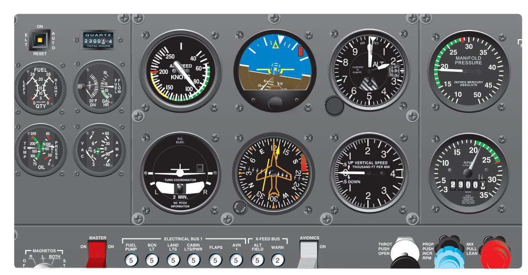
Imagine you are cruising along in solid IMC (Instrument Meteorological Conditions) when you notice something subtle: the heading indicator has stopped turning, and the artificial horizon shows a suspiciously wings-level picture even as you feel the aircraft beginning to bank. You have just experienced a vacuum system failure — and if you do not catch it and respond correctly, it can be fatal. Understanding how the vacuum system works, recognizing its failure, and knowing how to fly a "partial panel" using only the remaining instruments is a critical skill for every pilot, from the VFR student who inadvertently enters clouds to the instrument-rated aviator flying an IFR clearance in hard IMC.
The FAA's Instrument Flying Handbook (FAA-H-8083-15) dedicates significant coverage to partial-panel flying because gyroscopic instrument failures are among the most insidious emergencies a pilot can face. Unlike an engine failure — which announces itself loudly — a vacuum failure can be almost silent, tricking a pilot into trusting instruments that are slowly winding down and lying to them.
How the Vacuum System Works
Most light general aviation aircraft power two critical flight instruments through a vacuum (suction) system: the attitude indicator (AI) and the heading indicator (HI), also called the directional gyro. These instruments contain spinning gyroscopes. The gyro's rigidity in space and precession properties give them the ability to display aircraft attitude and direction reliably — but only as long as the gyro rotor is spinning at the required RPM.
The vacuum system typically consists of an engine-driven vacuum pump, a suction relief valve, a filter, and the gyroscopic instruments themselves. The pump creates a low-pressure (vacuum) environment; air rushing in through the instrument cases spins the gyro rotors, typically in the range of 10,000 to 15,000 RPM for proper operation, though exact figures vary by instrument and manufacturer. A suction gauge, usually measuring in inches of mercury (in. Hg), tells the pilot whether the system is producing adequate suction — commonly around 4.5 to 5.4 in. Hg, though always verify the specific aircraft's Pilot's Operating Handbook (POH) for exact values.
Some aircraft use a pressure system instead, which works on the same principle but pushes air through the instruments rather than pulling it. Either way, if the pump or its drive mechanism fails, the gyro rotors gradually spin down. This is the key danger: they do not stop instantly. A slowly dying gyro can give increasingly inaccurate readings for several minutes before it becomes obviously wrong, a period during which a pilot can be seriously misled.
Recognizing a Vacuum System Failure
Catching a vacuum failure early depends on cross-checking the suction gauge as part of your regular instrument scan. If the suction gauge reads zero or below the green arc while in flight, suspect an immediate vacuum failure. However, many pilots fail to include the suction gauge in their primary scan, which is why failure recognition can be delayed.
The classic symptom is a disagreement between gyroscopic and non-gyroscopic instruments. Your airspeed indicator, altimeter, vertical speed indicator (VSI), and magnetic compass are all non-gyroscopic (they rely on pitot-static air or magnetic fields) and will continue working normally. If your attitude indicator shows level flight but your altimeter is unwinding and your airspeed is increasing, trust the pitot-static instruments. If your heading indicator shows a steady heading but your magnetic compass is slowly rotating, the HI has likely failed.
The attitude indicator provides the most dramatic failure mode. As the gyro spins down, it may start to topple — tumbling to an extreme position and locking against its mechanical stops, often showing an extreme bank or pitch. At that point the instrument is obviously unreliable. But during spin-down, it may show only a slight, plausible-looking error. This subtle phase is where spatial disorientation accidents begin.
Partial Panel Flying Techniques
Flying "partial panel" means flying without the attitude indicator and heading indicator, relying instead on the magnetic compass, airspeed indicator, altimeter, and VSI — the so-called "needle, ball, and airspeed" instruments, though modern pilots use this expanded set. The turn coordinator (or turn-and-slip indicator), which is typically electrically powered (not vacuum-driven), becomes your primary bank reference.
The Turn Coordinator as Your Bank Reference
The turn coordinator shows rate of turn and, with its inclinometer (ball), coordinated flight. To maintain wings level, keep the miniature aircraft's wings level in the turn coordinator. To execute a standard-rate turn (3° per second), bank until the wingtip touches the standard-rate turn mark. Without an AI, the turn coordinator becomes your primary attitude reference in the roll axis, so it must be in your primary scan at all times.
The Magnetic Compass for Headings
The magnetic compass is your only remaining heading reference, but it has well-known errors that become critical during partial-panel work. The two most important are acceleration/deceleration error and northerly/southerly turning error. In the Northern Hemisphere, the compass lags when turning through north and leads when turning through south. The common memory aids — "ANDS" (Accelerate North, Decelerate South) for acceleration error, and "UNOS" (Undershoot North, Overshoot South) for turning error — help you compensate correctly when rolling out on a specific magnetic heading.
To roll out on a desired heading using the magnetic compass, you must lead or lag your rollout depending on the heading. For example, when turning to a northerly heading, start your rollout early (undershoot), because the compass will lag and read lower than your actual heading while you are banked. When turning to a southerly heading, let the compass overshoot past the desired heading before rolling wings level. Precise compass work takes practice; the IFH recommends practicing timed turns as an alternative, using a known standard rate (3° per second) and your clock to calculate how long a turn of a given number of degrees should take.
Pitch Control Without the Attitude Indicator
Without the attitude indicator, pitch is controlled by cross-referencing the altimeter, VSI, and airspeed indicator together. If the altimeter is unwinding and airspeed is rising, you are in a nose-low attitude — apply back pressure. If the altimeter is rising and airspeed falling, you are nose-high — apply forward pressure. The VSI confirms trend quickly (though with a slight lag), and the airspeed indicator gives immediate feedback. Trim is especially important on partial panel to reduce workload and allow a more stable platform for instrument cross-checking.
Why This Matters: The Graveyard Spiral
The insidious danger of vacuum failure in IMC is the graveyard spiral. When a pilot loses attitude reference and develops an unrecognized bank, the aircraft enters a descending spiral. As the nose drops, airspeed increases, and the pilot — feeling only centrifugal forces — may sense nothing wrong. If they pull back on the yoke to stop the altitude loss, they only tighten the spiral and accelerate the descent. Without recognizing the bank and leveling the wings first, the aircraft will overstress and potentially break up, or impact terrain at high speed. This is why the turn coordinator and non-gyroscopic instruments are literally life-saving tools in this scenario.
Key Numbers and Rules
- Normal suction range: approximately 4.5–5.4 in. Hg (confirm in your specific POH).
- Standard-rate turn: 3° per second, allowing a 180° turn in 60 seconds — used for timed turns on partial panel.
- Gyro spin-up/spin-down time: Attitude indicators may take several minutes to become unreliable after vacuum loss — the danger zone of plausible-but-wrong indications.
- Turn coordinator power source: Usually electrical, so it continues working during a vacuum failure — making it your primary bank instrument.
- Compass errors (Northern Hemisphere): ANDS — Accelerate North, Decelerate South; UNOS — Undershoot North, Overshoot South for turns.
- Immediate action: Recognize failure (suction gauge + instrument cross-check), cover or ignore failed instruments, declare emergency if IMC and not instrument-rated, and navigate toward VMC or request ATC assistance.
Memory Aid
UNOS — Undershoot North, Overshoot South: When turning to a northerly heading in the Northern Hemisphere, begin your rollout before the compass reaches the desired heading (undershoot). When turning to a southerly heading, allow the compass to pass beyond the desired heading before rolling out (overshoot). This compensates for the compass's inherent northerly turning lag and southerly turning lead caused by magnetic dip. This turning error is greatest on north and south headings and diminishes to zero on east and west headings.
ANDS — Accelerate North, Decelerate South: When the aircraft accelerates, the compass briefly swings toward a northerly indication; when it decelerates, it swings toward south. This acceleration/deceleration error is most pronounced on east or west headings and diminishes to zero near north or south — the opposite heading pattern from the UNOS turning error described above.
Common Test Traps
- Assuming the turn coordinator is vacuum-powered: It is typically electrically powered and will continue working after a vacuum failure — a favorite exam trick. Always verify with your aircraft's POH.
- Trusting a slowly failing gyro: The AI and HI do not fail instantly. The test may describe a subtle disagreement; recognize that the pitot-static instruments and turn coordinator are telling the truth.
- Forgetting UNOS for compass turns: Many students remember ANDS (acceleration error) but forget the turning error compensation. Exam questions about rolling out on a northerly heading expect you to know to lead the rollout.
- Confusing which instruments are affected: Only the AI and HI are vacuum-driven in most light aircraft. The airspeed indicator, altimeter, VSI, magnetic compass, and (usually) turn coordinator remain fully functional — these are your partial-panel tools.
- Not declaring an emergency: A VFR-only pilot caught in IMC with a vacuum failure should immediately contact ATC and declare an emergency. Squawking 7700 is appropriate if not already in radar or radio contact with ATC, per AIM guidance on transponder emergency codes — once in contact, follow ATC instructions regarding the code to use. The FAA knowledge test and practical test standards both expect pilots to recognize when ATC assistance is the correct action.