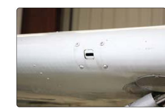
A stall warning vane and an angle-of-attack (AOA) probe both work by detecting the actual direction of airflow relative to the aircraft's wing or fuselage. In clean, dry air these devices function reliably with no extra attention. But introduce even a thin layer of ice or a heavy coating of freezing drizzle, and a mechanical vane can freeze in place or an AOA probe port can become blocked — leaving the flight crew with false data or no stall warning at all, precisely when it is needed most. Electrically heated versions of these sensors are therefore not accessories; they are life-safety components on any aircraft certificated for flight into known icing conditions. As an AMT preparing for the Airframe knowledge test and certificate, you must understand how each sensor type works, how the heating element integrates into the airframe electrical system, and how to recognize, troubleshoot, and document failures.
How Stall Warning Vane Systems Work
A stall warning vane (sometimes called an angle-of-attack vane or leading-edge vane) is a small, aerodynamically shaped paddle mounted on the wing leading edge, fuselage nose section, or another location exposed to freestream airflow. As the aircraft's angle of attack (AOA) increases, the upwash of air ahead of the wing rotates progressively upward. The vane follows this upwash. When the upwash angle reaches a value corresponding to an AOA near the critical stall angle, the vane triggers a switch — typically a micro-switch or reed switch — that activates the cockpit stall warning horn, light, or stick shaker system.
The vane pivots freely on a low-friction bearing. Because it responds to the direction of local airflow rather than airspeed directly, it provides a stall warning that is largely independent of aircraft weight, configuration changes, or density altitude. The system is elegantly simple: no air data computer is needed for the basic function. However, if the vane freezes in a position that does not reflect the true upwash angle — especially if it freezes in a depressed, nose-down position suggesting low AOA — the stall warning system becomes inoperative at the exact moment it should be screaming at the pilot.
How AOA Probe Systems Work
More sophisticated aircraft use a dedicated AOA probe (also called an alpha vane or angle-of-attack sensor) that continuously feeds an electrical signal to an AOA indicator, flight management system, or stall protection computer. AOA probes come in two primary designs: the rotating vane type and the differential pressure (pneumatic) type.
The rotating vane type resembles the stall warning vane but drives a precision rotary potentiometer or synchro transmitter, producing a continuous analog or digital angle output rather than a simple on/off switch signal. The pneumatic type uses two small ports arranged at different positions on a probe body — one facing slightly upward and one facing slightly downward into the airstream. The difference in total pressure between the two ports is proportional to the AOA. This differential pressure signal is converted by a transducer into an electrical AOA signal. Either design must maintain an unobstructed, ice-free interface with the airflow to remain accurate.
Heating Element Design and Integration
Heating for both vane-type and probe-type sensors is accomplished with embedded resistance heating elements — essentially nichrome or similar alloy wire or foil elements encapsulated in the body and pivot assembly of the sensor. When energized, these elements conduct enough electrical current to raise the surface temperature of the sensor well above the freezing point of water, shedding any ice accumulation and preventing new ice from forming.
The heating circuit is powered from the aircraft's electrical system through a current-limiting circuit breaker, and the power source varies by airframe — many general aviation and business aircraft use DC power, while numerous transport-category aircraft power AOA probe and stall warning vane heat circuits from 115V AC or 26/28V AC sources instead of, or in addition to, DC, depending on the specific aircraft type and system design. The circuit breaker rating must match the sensor manufacturer's specification; an improperly rated breaker can either nuisance-trip during normal operation or fail to protect the wiring harness during a fault. On many aircraft the AOA probe heat and stall warning vane heat are separate circuits, each with its own breaker, so that a single fault does not simultaneously disable all stall protection.
On turbine-powered transport aircraft, automatic control of probe heat is common. A dedicated controller or the aircraft's ice protection control module energizes probe and vane heat whenever the aircraft is powered, and on many designs the system uses dual heat levels tied to ground versus flight operation — often a reduced or lower-power ground setting to prevent overheating when there is little or no airflow to carry heat away, and full power in flight where airspeed provides cooling airflow. A fault annunciation system monitors the heating circuit current — an open-circuit condition draws no current and illuminates a warning, while a short circuit draws excessive current and trips the breaker, also generating a caution or warning. Pilots and maintenance technicians must never assume the heater is working simply because no light is on; the correct check is to verify current draw with an ammeter or use the aircraft's built-in test (BITE) system.
Why It Matters: Safety and Certification
The FAA requires that aircraft approved for flight into known icing conditions (FIKI) maintain the full function of all stall warning and angle-of-attack sensing systems throughout the icing environment. If the stall warning vane heat or AOA probe heat is inoperative, the aircraft may not be dispatched into known icing, and in many cases the aircraft's minimum equipment list (MEL) will require the icing environment to be avoided entirely until the system is repaired.
Historical accident investigations have confirmed that frozen or obstructed AOA and stall warning sensors have contributed to loss-of-control accidents. A vane frozen in the low-AOA position will never trigger the stall warning, giving the crew false confidence at critically low airspeeds. Conversely, a vane frozen in a high-AOA position can create continuous false stall warnings, distracting or confusing the crew. Neither failure mode is acceptable.
Maintenance Practices and Inspection
AMTs must follow the aircraft maintenance manual (AMM) precisely when inspecting, testing, and replacing heated vanes and AOA probes. Key maintenance tasks include:
- Continuity and resistance checks: An ohmmeter applied across the heating element terminals verifies the element is intact. Compare the measured resistance to the manufacturer's specification; a significantly higher resistance suggests a partially broken element, while infinite resistance indicates a complete open circuit.
- Current draw verification: Apply aircraft voltage and measure current with a calibrated ammeter. Correct current draw (typically specified in amps in the AMM) confirms the heater is producing the designed wattage.
- Functional heat test: On many aircraft the AMM directs the technician to energize the heat and physically verify (by touch — carefully, as elements get very hot) or with a thermocouple that the sensor surface is heating. Do NOT leave a heated probe energized on the ground for extended periods without airflow; prolonged ground operation at full power can overheat and damage the sensor body or surrounding structure.
- Vane freedom of movement: Manually deflect the vane through its full range of travel and verify it returns freely. Stiff or binding movement indicates contamination, corrosion, or bearing damage — all grounds for replacement.
- Wiring harness inspection: Chafing, cracked insulation, and corroded terminals in the probe wiring are common failure points. Inspect the full length of the harness, paying particular attention to grommets and areas where the wire passes through structure.
- Switch function (vane systems): Actuate the vane to the stall warning trigger position and verify the cockpit warning activates. Release and verify it deactivates. This simple test confirms the full signal path from vane to cockpit.
Key Numbers and Rules
- Heated AOA probes and stall warning vanes are powered from a dedicated electrical circuit, with breakers sized precisely per the manufacturer's specification; the power source (DC, or 115V/26V/28V AC) varies by aircraft type, so always confirm the specific circuit voltage and type in the applicable AMM rather than assuming a single standard.
- Ground heating time limits, where specified, vary significantly by aircraft and manufacturer and are not a standardized FAA figure — always consult the applicable AMM limitations section rather than relying on a generic time value.
- Resistance values of heating elements vary considerably by probe design and manufacturer; always compare a measured resistance to the specific value published in the manufacturer's maintenance data rather than a generic range.
- Aircraft dispatched under an MEL with probe heat inoperative typically require flight to remain outside of icing conditions as defined in 14 CFR Part 25 Appendix C or the applicable operational rule.
- Repairs and replacements must be documented in the aircraft maintenance records per 14 CFR Part 43, and a return-to-service endorsement is required before flight.
Common Test Traps
- Confusing the two failure modes: The FAA may ask what happens when a stall warning vane freezes in the low-AOA position. The answer is that stall warning is LOST — the system will never trigger, even at actual stall AOA. Do not confuse this with a nuisance warning caused by freezing in the high-AOA position.
- Assuming heat is ON because no warning light exists: Many aircraft only alert the crew to a heater failure via a dedicated caution light or EICAS message. If that monitoring circuit itself fails, the heater can be inoperative with no indication. BITE checks and maintenance verification are the only reliable confirmation.
- Overlooking ground operation limits: Technicians sometimes leave probe heat energized during extended ground troubleshooting. Without airflow cooling, the element can overheat. The AMM ground-operation time limit, when specified for a given aircraft, is a hard limit, not a guideline.
- Interchanging AOA probe types: A rotating vane AOA sensor and a differential-pressure AOA probe are NOT interchangeable. Each produces a different type of signal and requires a matched indicator or computer input. Using the wrong sensor type will produce erroneous AOA readings even if the unit is electrically functional.
- Neglecting the wiring harness: On knowledge tests and practical exams, questions about AOA probe system troubleshooting often focus on the complete circuit. An intermittent open in the wiring harness produces the same no-heat symptom as a failed heating element — resistance-check the harness as well as the element before condemning the sensor.