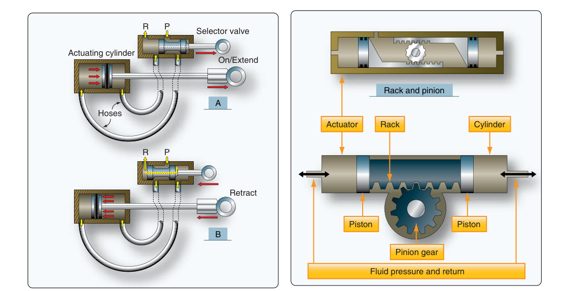
Every time a pilot raises the landing gear, extends the flaps, or applies the brakes, hydraulic actuators are doing the heavy lifting. These devices sit at the working end of the hydraulic system, converting pressurized fluid energy into precise mechanical motion. Without actuators, all the pumps, reservoirs, and valves in an aircraft's hydraulic system would have nothing useful to accomplish. Understanding how linear and rotary actuators work — and how to inspect and maintain them — is a core competency for every Aviation Maintenance Technician working on aircraft airframes.
Hydraulic actuators fall into two broad families based on the type of motion they produce: linear actuators, which push or pull in a straight line, and rotary actuators, which produce turning motion through a limited arc. Both families obey the same fundamental principle — Pascal's Law — but they are built differently and suited to different jobs on the aircraft.
Pascal's Law: The Foundation of Actuator Operation
Pascal's Law states that pressure applied to a confined fluid is transmitted equally in all directions throughout the fluid. In practical terms, this means that when a hydraulic pump builds pressure in the system, that pressure acts with equal force on every square inch of piston or vane area inside an actuator. Force equals pressure multiplied by area (F = P × A). A relatively modest hydraulic system pressure — typically 1,000 to 1,500 psi in light aircraft and commonly 3,000 psi in transport-category aircraft, with some newer aircraft using 5,000 psi systems — can be multiplied into thousands of pounds of mechanical force simply by increasing the piston area. This mechanical advantage is what makes hydraulics indispensable for operating large, heavily loaded components like main landing gear and flight control surfaces.
Linear Actuators: Straight-Line Power
A linear actuator — also called a hydraulic cylinder or actuating cylinder — produces motion along a single axis. The basic assembly consists of a cylindrical housing, a piston, a piston rod, end caps with fluid ports, and seals throughout. Pressurized fluid enters one port, acts against the face of the piston, and drives the piston (and its attached rod) along the cylinder bore. When the direction of movement must reverse, fluid is directed to the opposite port while the first port is connected to return.
Single-Acting Cylinders
A single-acting cylinder has only one fluid port. Hydraulic pressure drives the piston in one direction; a mechanical spring (or gravity, or an aerodynamic load) returns it in the other. These are used where the return stroke requires very little force — for example, in some simple latch or lock mechanisms. Because only one side of the piston is pressurized, the output force is the same in both directions only if a spring strong enough to do the job is fitted, which is rarely ideal for high-load applications.
Double-Acting Cylinders
The double-acting cylinder is by far the more common type in aircraft. It has two fluid ports — one at each end of the cylinder. Pressurizing the cap end drives the rod out (extension stroke); pressurizing the rod end drives the rod back in (retraction stroke). Because both strokes are powered by hydraulic pressure, large loads can be moved in either direction with equal reliability. Landing gear actuators and flight control actuators are almost always double-acting.
There is an important force asymmetry in double-acting cylinders worth noting: on the extension stroke, pressure acts on the full piston area. On the retraction stroke, pressure acts on the piston area minus the cross-sectional area of the piston rod. This means the retraction stroke produces slightly less force than the extension stroke at the same pressure. Aircraft designers account for this when sizing actuators.
Actuator Seals and End-of-Travel Cushioning
Seals are critical to actuator performance and longevity. Static seals (O-rings seated in grooves) prevent leakage at fixed joints such as end cap threads. Dynamic seals (lip seals, U-cup seals, or piston rings) must allow the piston and rod to move while still preventing fluid from bypassing the piston or escaping past the rod. Worn or damaged seals are the most common cause of actuator internal and external leakage. Many actuators incorporate end-of-travel cushioning: as the piston approaches the end of its stroke, a small cushion plunger enters a metered orifice, trapping a pocket of fluid that decelerates the piston gradually. This prevents damaging metal-to-metal impact at high speeds and reduces structural shock loads — especially important in landing gear systems where actuators move large masses at relatively high velocity.
Rotary Actuators: Converting Pressure to Torque
A rotary actuator converts hydraulic pressure directly into rotational force (torque) without needing a separate linkage to translate linear motion into rotation. This makes them compact and mechanically elegant where a rotating output is needed. Aircraft applications include nosewheel steering, flap drive systems, and some cargo door mechanisms.
Vane-Type Rotary Actuators
The most common aircraft rotary actuator uses one or more vanes attached to a central shaft inside a circular housing. Hydraulic pressure enters one side of the vane chamber, pushing the vane and rotating the shaft. The opposite port serves as the return. Because the vane can only travel through the arc of the housing — typically 90° to 270° depending on design — these are called limited-rotation actuators. They are ideal for nosewheel steering, where the nose gear must be turned through a defined arc but does not need to rotate continuously.
Piston-Type Rotary Actuators
Some rotary actuators use a rack-and-pinion or helical-spline arrangement where a hydraulically driven linear piston meshes with a toothed shaft to produce rotation. These are mechanically robust and can generate very high torques, making them suitable for large cargo doors and retractable airstairs on transport-category aircraft.
Why Actuator Selection and Condition Matter
The actuator is the final force-producing element in the hydraulic circuit. If an actuator leaks internally — fluid bypassing the piston from high-pressure to low-pressure side — the component it drives will drift, move sluggishly, or fail to hold position under load. A landing gear that slowly creeps down in flight or brakes that fade under sustained pedal pressure often trace back to a faulty actuator seal rather than to a problem with the pump or valve. External leakage from a damaged rod seal or cracked housing poses a fire hazard and will eventually result in low fluid level, threatening the entire hydraulic system.
During inspection, the AMT should check actuator attachment points for cracks, elongated bolt holes, and correct torque on retaining hardware. Rod ends and clevises should be checked for wear, corrosion, and correct safety-wiring or cotter-pin installation. The rod itself should be inspected for nicks and scratches — even minor surface damage can destroy a rod seal within a few cycles. Chrome-plated rods that show pitting or corrosion through the plating must be replaced or re-chromed before return to service.
Key Numbers and Rules
- Typical light aircraft hydraulic pressure: 1,000–1,500 psi; transport-category aircraft commonly operate at 3,000 psi, with some newer aircraft using 5,000 psi systems.
- Force formula: F = P × A — force in pounds equals pressure in psi multiplied by piston area in square inches.
- Retraction vs. extension force: The retraction stroke of a double-acting cylinder produces less force than the extension stroke because the rod reduces the effective piston area.
- Vane actuator rotation range: Typically limited to 90°–270° of arc depending on housing design.
- Seal materials: Must be compatible with the hydraulic fluid type (MIL-H-5606 petroleum-based, MIL-H-83282 fire-resistant, or Skydrol phosphate ester) — mixing incompatible seals and fluid types rapidly destroys seals.
- Internal leakage check: With the actuator at end-of-travel and system pressure applied, any movement of the output rod or shaft indicates internal seal bypass and requires maintenance.
Common Test Traps
- Confusing single-acting and double-acting cylinders: Remember that single-acting cylinders are powered in only one direction — the return is accomplished by spring, gravity, or an external load, not by hydraulic pressure. The FAA tests this distinction directly.
- Ignoring the rod-area effect: Many students assume both strokes of a double-acting cylinder produce equal force. They do not — the retraction stroke always has a smaller effective area because the rod occupies part of the piston face.
- Misidentifying rotary actuator limits: Rotary (vane-type) actuators produce limited rotation — they are not motors and cannot spin continuously. Hydraulic motors are a separate category of device.
- Overlooking fluid compatibility with seal materials: Installing seals designed for petroleum-based fluid in a Skydrol system (or vice versa) causes rapid seal deterioration. Always verify compatibility before installation.
- Neglecting cushioning devices: End-of-travel cushions are not optional extras — they protect both the actuator and the structure it connects to from shock loads. A missing or bypassed cushion plunger can cause rapid structural fatigue at attachment points.