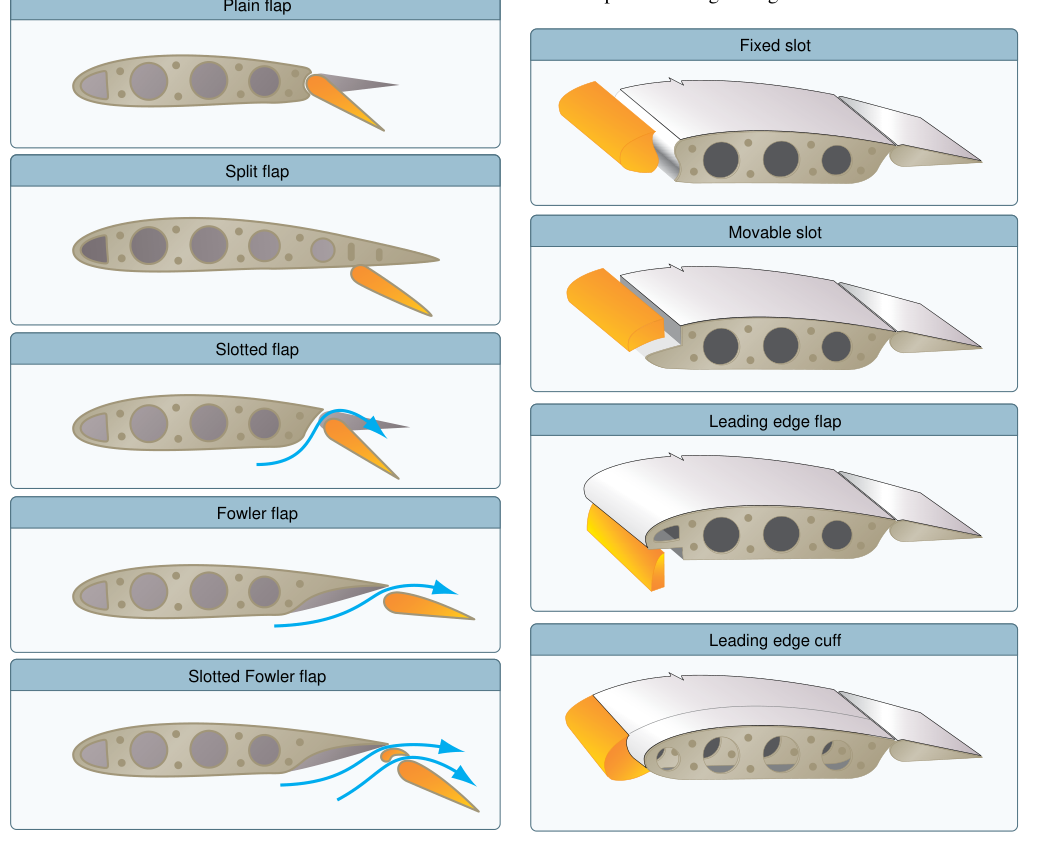
High-lift devices are mechanical systems integrated into the wing structure that temporarily and dramatically increase the wing's maximum lifting capability during takeoff, approach, and landing — phases of flight where the aircraft must operate at airspeeds far below its cruise design point. Transport-category airplanes depend on two primary families of high-lift hardware: leading-edge devices, most commonly slats and Krueger flaps, and trailing-edge flap systems, which range from simple hinged panels to complex triple-slotted Fowler assemblies. Mastery of what each device contributes aerodynamically, the precise numbers that govern their use, and how the two systems interact under both normal and abnormal conditions is tested directly on the ATP Airline Transport Pilot Knowledge Test and is operationally critical every time a heavy jet departs or arrives.
The Physics of Lift Limitation
To appreciate why high-lift devices exist, start with the fundamental lift equation: L = CL × q × S, where CL is the coefficient of lift, q is dynamic pressure (½ρV²), and S is wing area. During cruise, a transport wing is optimized for low drag at high speed and high altitude, which means relatively thin airfoil sections with low camber and modest area. At low speeds the dynamic pressure q drops sharply, so without intervention CL must rise steeply to maintain level flight — but every airfoil has a maximum CL beyond which the boundary layer separates from the upper surface and the wing stalls. High-lift devices attack this problem from two directions simultaneously: leading-edge devices raise the critical angle of attack at which stall occurs, while trailing-edge devices raise the value of CL max achievable before that stall. The combination can substantially increase the effective maximum lift coefficient compared to the clean wing configuration, which is why the same wing that cruises efficiently at Mach 0.82 can also approach at 140 knots without departing controlled flight.
Leading-Edge Devices: Keeping the Flow Attached
Slats
A leading-edge slat is a movable airfoil element hinged at or near the wing's leading edge. When commanded to extend — either mechanically via screw-jack drives or hydraulically — the slat translates forward and rotates downward, opening a slot between the slat's trailing edge and the main wing's leading edge. High-energy air from the high-pressure region beneath the wing accelerates through this slot and is directed tangentially onto the upper surface of the main wing. This re-energizes the boundary layer, replacing the low-momentum air that would otherwise separate prematurely. The aerodynamic result is that flow remains attached at angles of attack that would stall the clean wing, effectively raising the stall angle of attack. Because stall occurs at a higher pitch attitude, a lower indicated airspeed is achievable in steady flight, reducing VS and therefore VREF and V2.
Krueger Flaps
Krueger flaps are an alternative leading-edge device used on some transport jets, particularly on inboard wing sections where the leading edge may house fuel tanks that preclude a slat mechanism. Rather than opening a slot, a Krueger flap folds outward from the lower surface of the leading edge, increasing the chord length and overall camber of that wing section. They increase CL max primarily through the camber effect rather than boundary-layer re-energization, so they are generally less effective than slats at very high angles of attack but are mechanically simpler for certain structural configurations. Many wide-body designs use slats outboard and Krueger flaps inboard as a hybrid arrangement.
Trailing-Edge Flap Systems: Raising CL max and Adding Drag
Trailing-edge flaps work by deflecting a surface downward along the rear portion of the wing, increasing both the effective camber of the airfoil and — in Fowler designs — the total planform area S. This raises CL max significantly. The drag increase that accompanies flap extension is intentional and operationally useful: it steepens the approach path and allows the engines to operate at higher thrust settings for better response to a go-around command.
Flap Types Used in Transport Aircraft
- Plain flaps — a simple hinged panel at the trailing edge. Effective but moderate in lift gain; used mainly on smaller aircraft or as a component of more complex systems.
- Split flaps — only the lower surface of the trailing edge deflects; produces high drag with a relatively modest lift increase and is rarely found on modern transport jets.
- Fowler flaps — the dominant design on large jets. The flap panel first translates rearward on tracks before rotating down, simultaneously increasing wing area S and camber. The rearward translation exposes a slot, re-energizing upper-surface flow. At partial settings Fowler flaps yield a large CL increase with relatively modest drag — ideal for takeoff. At full deflection the large rotational angle produces the high drag needed for landing.
- Double- and triple-slotted Fowler flaps — multiple panel segments each separated by an aerodynamic slot; each slot re-energizes the boundary layer over the next downstream panel, allowing extreme deflection angles without separation. Triple-slotted systems can generate substantially higher CL max values than simpler flap designs, enabling very low approach speeds on large aircraft.
Integrated Slat-Flap Schedules and System Architecture
On virtually all modern transport jets the leading-edge and trailing-edge devices are mechanically or electronically interconnected through a flap/slat control system. A single flap lever or switch in the cockpit commands both systems through a predetermined schedule — for example, advancing the flap handle to Flaps 5 may simultaneously extend the trailing-edge panels five degrees and partially extend the leading-edge slats. Full extension of both systems is required for the landing configuration. Separate position indicators for leading-edge and trailing-edge devices allow the crew to detect asymmetries or split conditions. Hydraulic power drives most slat and flap actuators, with alternate electric or pneumatic modes available for abnormal operations. Continuous position monitoring feeds the flight management system and performance computers, which in turn verify that takeoff and approach speeds are computed for the actual, confirmed flap configuration.
Regulatory and Performance Implications
Under 14 CFR Part 25, transport-category airplanes must demonstrate takeoff, en-route, and landing performance with defined high-lift configurations. The landing reference speed VREF must not be less than 1.23 times the reference stall speed VSR in the landing configuration per 14 CFR 25.125 — a margin that accounts for gusts and maneuvering but still depends on maximum CL being achievable reliably. V2 (takeoff safety speed) must not be less than 1.13 VSR, or 1.08 VMC, whichever is greater, in the takeoff configuration per 14 CFR 25.107. These numbers directly reflect the performance that high-lift devices make possible. Approved flap configurations for takeoff are published in the Airplane Flight Manual and balance the trade-off between reduced stall speed (more flap) and reduced drag for obstacle clearance (less flap). Most operators specify Flaps 5, 10, or 15 for takeoff and full flaps for landing, but exact values vary by aircraft type.
Key Numbers and Rules
- VREF ≥ 1.23 VSR in the landing configuration per 14 CFR 25.125.
- V2 ≥ 1.13 VSR (or 1.08 VMC, whichever is greater) in the takeoff configuration per 14 CFR 25.107.
- Slats raise the critical angle of attack, with the exact increase depending on geometry and deflection angle.
- Triple-slotted Fowler systems achieve substantially higher CL max values in the landing configuration compared to the clean wing, though FAA handbooks do not standardize a specific numeric figure for either.
- Flap asymmetry (unequal left/right extension) generates a roll moment proportional to the lift differential — handled per the applicable abnormal (non-normal) checklist procedure, with classification and severity varying by aircraft type and manufacturer.
- Leading-edge device disagreement (slats not extending with flap command) typically produces a distinct cockpit annunciation and may invalidate published V-speeds — requiring reference to abnormal checklists before continuing the approach.
Common Test Traps
- Slats delay the stall — they do not prevent it. The critical angle of attack is raised, but exceed it and the wing stalls. On some aircraft an uncommanded slat retraction in flight can cause an abrupt, unannunciated stall at a seemingly safe airspeed.
- Fowler flaps increase wing area, not just camber. Test questions asking which flap type produces the greatest CL increase with minimum additional drag at partial deflection are targeting the Fowler or slotted Fowler — not plain or split flaps.
- Partial flap settings produce more lift relative to drag; full-flap settings emphasize drag. Confusing a Flaps 15 takeoff chart with a Flaps 40 landing chart is a classic performance-calculation error.
- Leading-edge and trailing-edge devices are separate systems that must be cross-checked. A trailing-edge flap indication in the landing configuration does not guarantee that leading-edge slats have extended — always verify both position indicators before accepting approach speeds.
- Flap overspeed limits (VFE) differ by flap position. Higher deflection angles have lower VFE values. Exceeding VFE can cause structural damage to flap tracks, actuators, and the flap panels themselves.