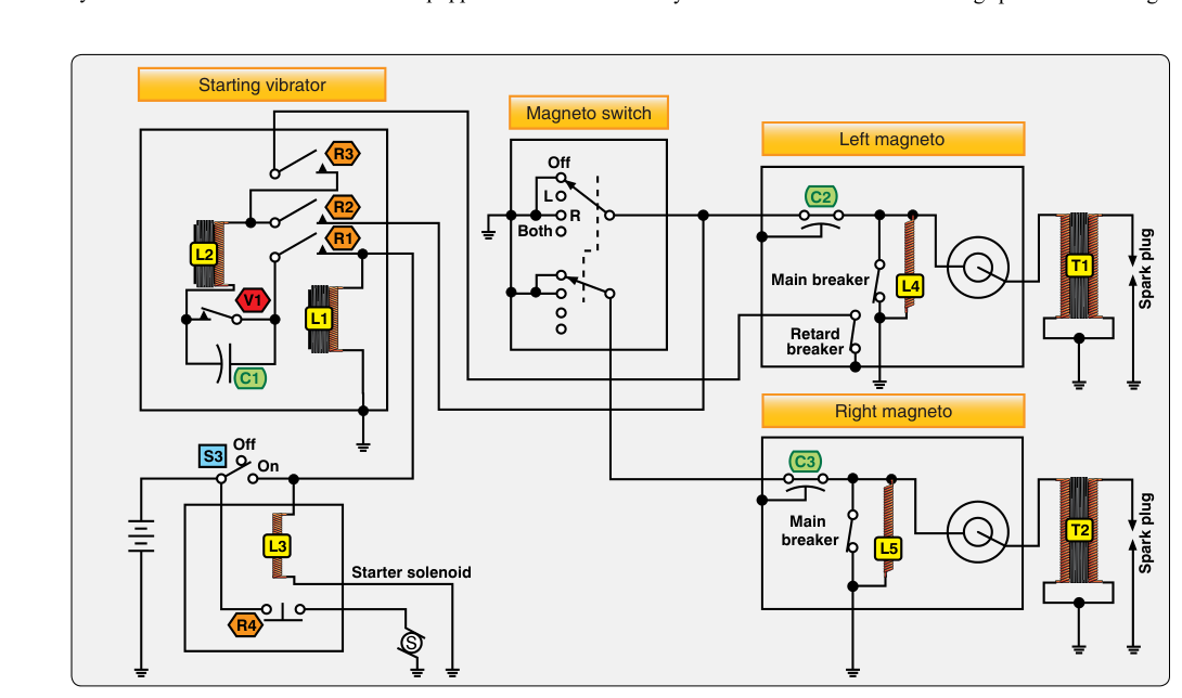
Ignition reliability is one of the most safety-critical aspects of any aircraft powerplant. A failure to ignite the fuel-air mixture at precisely the right moment can mean a rough-running engine, a sudden power loss, or a complete in-flight shutdown. To understand how aircraft ignition systems achieve the voltage levels needed to fire spark plugs under compression, it is essential to distinguish between the two fundamental circuit architectures: the high-tension system and the low-tension system. Each design solves the same fundamental problem — delivering a spark of sufficient energy to the plug — by using a different strategy for where and how the voltage transformation occurs.
Most technicians encounter high-tension systems routinely because they are far more common in general aviation aircraft. Low-tension systems, while less widespread today, appear on some larger, older radial-engine installations and represent an important chapter in ignition engineering. Understanding the principles of both systems not only prepares you for the AMT Powerplant knowledge test but also equips you to recognize potential failure modes and troubleshoot ignition faults in the field.
How High-Tension Ignition Systems Work
In a high-tension ignition system, the magneto itself generates and transforms voltage up to its final, firing value — typically in the range of 15,000 to 20,000 volts or higher — before that voltage is distributed to each spark plug. The magneto contains a rotating permanent magnet, a primary coil, a secondary coil, breaker points (or an electronic equivalent), and a condenser. As the magnet spins, it induces a current in the primary winding. When the breaker points open, the primary circuit collapses rapidly. Because the secondary winding has many more turns of wire than the primary, this collapsing magnetic field induces a very high voltage in the secondary — Faraday's law of electromagnetic induction at work.
That high-voltage output is then routed through a distributor inside the magneto, which directs the pulse to the correct spark plug in firing-order sequence. From the distributor, each plug receives its voltage through a high-tension lead — a heavily insulated wire designed to contain the very high electrical potential without arcing to surrounding structure or to adjacent leads. These leads terminate at the spark plug, where the voltage jumps across the electrode gap and ignites the compressed fuel-air charge.
The defining characteristic of the high-tension system is that the high voltage must travel the entire length of the ignition lead before it reaches the plug. On a large engine with long lead runs — especially on a radial engine with cylinders arranged radially at varying distances — the harness wire must carry 15,000 V or more over distances that can be several feet. This creates two important maintenance concerns: lead insulation breakdown and corona (electrical leakage). Any nick, crack, moisture intrusion, or age-related deterioration in the insulation allows current to escape before it reaches the plug, resulting in a weak or absent spark at that cylinder.
How Low-Tension Ignition Systems Work
The low-tension ignition system takes a fundamentally different approach. The magneto still generates an alternating current, but it outputs only a relatively low voltage — roughly 200 to 400 volts — and this low-tension current is what travels through the distribution harness to each cylinder. At or near each individual cylinder, a step-up transformer (sometimes called a secondary coil unit or individual coil unit) boosts the voltage to the 15,000 V range required to fire the spark plug. The transformation happens locally, right at the point of use.
Because the wiring harness carries only low voltage between the magneto and the cylinder-mounted coils, the insulation requirements for that portion of the circuit are dramatically reduced. The wires can be lighter, cheaper, and less susceptible to the high-voltage insulation failures that plague long high-tension lead runs. This was a practical engineering advantage on large radial engines — such as those used in World War II–era heavy bombers and transports — where cylinder banks were spread across a large diameter and lead runs would otherwise have been very long.
The trade-off is mechanical and component complexity. Instead of one coil inside the magneto, a low-tension system requires an individual transformer at each cylinder. More components mean more potential points of failure, and the cylinder-mounted coils are exposed to heat, vibration, and oil contamination in an environment that is harsher than the inside of a magneto housing. Maintenance access can also be more challenging.
Why It Matters for Airworthiness and Maintenance
Understanding which type of system you are working on directly shapes your inspection and troubleshooting approach. Most Part 91 general aviation aircraft use high-tension systems, and a significant portion of AMT Powerplant work involves inspecting and servicing high-tension ignition harnesses and leads. The FAA's Aviation Maintenance Technician Handbook — Powerplant (FAA-H-8083-32) describes the inspection of ignition leads for insulation condition as a routine maintenance task. Technicians check for chafing, burned insulation, cracked rubber boots at the spark plug end, and evidence of carbon tracking, which appears as a fine, sooty path along which current has been leaking rather than jumping the plug gap cleanly.
A magneto timing check — verifying that the points open (or the electronic trigger fires) at precisely the correct crankshaft position — is equally critical in both system types, because the timing determines when the spark occurs relative to piston position. Incorrect timing leads to detonation, preignition, power loss, or engine damage. On high-tension systems, the timing check is performed at the magneto. On low-tension systems, timing the magneto itself is still necessary, but the secondary coil units introduce additional variables.
Dual-magneto systems — the industry standard for certificated aircraft engines — provide redundancy regardless of whether the architecture is high-tension or low-tension. Each magneto powers one set of spark plugs per cylinder (one top plug, one bottom plug in most horizontally opposed engines). The magneto checks performed during run-up — switching from BOTH to LEFT and then to RIGHT — verify that each magneto can sustain combustion independently, confirming system redundancy before flight.
Key Numbers and Rules
- High-tension output voltage: approximately 15,000–20,000 V (can exceed 20,000 V under high manifold pressure or altitude conditions).
- Low-tension distribution voltage: approximately 200–400 V in the harness, stepped up to firing voltage at each cylinder coil.
- Magneto switch positions: BOTH, LEFT, RIGHT, and OFF — in the OFF position, the primary circuit is grounded (not open), rendering the magneto incapable of producing a spark and making the engine safe to handle.
- Typical magneto RPM drop check: most manufacturers specify a maximum drop of approximately 125 RPM on a single magneto, and a differential between left and right of no more than about 50 RPM, though specific limits vary by engine make and model — always consult the engine manufacturer's maintenance manual.
- P-lead function: the primary lead (P-lead) connects the primary coil to ground through the magneto switch. A broken or disconnected P-lead means the magneto remains electrically HOT even when the cockpit switch is in the OFF position — a serious safety hazard during preflight and maintenance.
- Lead insulation testing: high-tension leads are commonly tested with a high-voltage lead tester that checks insulation resistance while simulating operating conditions; minimum resistance values are specified in the manufacturer's instructions for continued airworthiness.
Common Test Traps
- OFF does not mean open: Many students assume the magneto switch in the OFF position opens the primary circuit. In fact, OFF grounds the primary — it is a shorting switch, not an open switch. An open P-lead (broken wire) gives the same electrical condition as the switch being in the BOTH or ON position, making the propeller dangerous.
- Confusing which voltage travels in each system: In a high-tension system, the high voltage travels in the lead to the plug. In a low-tension system, the high voltage is created locally — the lead carries low voltage. This is a commonly tested distinction.
- Assuming all GA aircraft use high-tension systems: The test may reference low-tension systems in the context of large radial engines; know that both types exist and why each was used.
- Ignoring the condenser's role: The condenser (capacitor) in the magneto primary circuit prevents arcing across the breaker points as they open and allows the magnetic field to collapse rapidly. A failed condenser results in eroded points and a weak spark — students often overlook this component when diagnosing magneto problems.
- Mistaking corona discharge for insulation failure: Corona is a form of high-voltage leakage from the surface of a lead that may not be visible without specialized equipment; it can cause radio interference (magneto noise) and a weak spark without an obvious physical defect in the lead insulation visible to the naked eye.