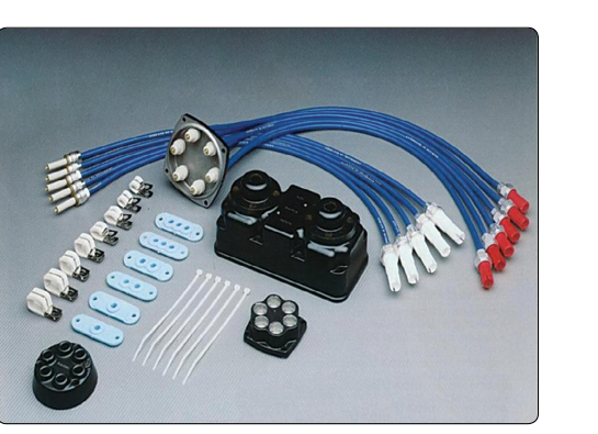
The ignition harness is the network of shielded, high-voltage cables that connects each magneto output to its corresponding spark plugs. Every time the magnetos fire — which, at cruise RPM, can be thousands of times per minute — the harness must faithfully deliver a high-voltage spike, typically in the range of about 8,000 to 20,000 volts depending on the system and plug gap, to each plug without leaking energy to the airframe or atmosphere. Because the harness operates under extreme electrical stress, vibration, heat, and moisture, it is one of the components that maintenance technicians most frequently inspect, test, and replace on reciprocating aircraft engines. A faulty harness can produce hard starting, rough running, high magneto drop during run-up, or complete ignition failure on an affected cylinder — any of which can compromise flight safety.
This article covers the construction of a typical aircraft ignition harness, the methods used to inspect and test it, the regulatory and manufacturer guidance governing its replacement, and the practical skills an AMT must bring to each task. All procedures must be performed in accordance with the applicable engine manufacturer's maintenance manual, aircraft maintenance manual, and 14 CFR Part 43.
Construction and Function of the Ignition Harness
A typical harness consists of individual ignition leads, sometimes called ignition cables or spark plug leads, assembled into a protective conduit or manifold. Each lead has three main layers: a central conductor (usually a stranded or spiral-wound resistive wire that suppresses radio-frequency interference), a high-voltage insulation layer made of silicone rubber or a similar dielectric material, and an outer metallic braid shield that is bonded to the engine for electromagnetic shielding and safety.
The harness connects at one end to the distributor block or distributor gear inside the magneto and at the other end to each spark plug through an elbow (also called a cigarette or ignition lead end) that includes a contact spring and a rubber boot. The elbow slips over the spark plug terminal insulator and makes spring-loaded electrical contact. The metallic shield is typically grounded at the magneto end, through the distributor block and magneto case, providing the shielding path back to the engine.
Modern harnesses are often supplied as complete, pre-manufactured assemblies specific to the engine model. Field-fabricated harnesses, where individual leads are cut to length and fitted with connectors by the technician, are also acceptable when performed in accordance with approved data, but this practice requires careful attention to conductor continuity, insulation integrity, and proper end-fitting installation.
Inspection Methods
Harness inspection is normally accomplished at each scheduled inspection interval, at spark plug removal and installation, and whenever ignition anomalies are reported. A thorough inspection includes both visual and electrical checks.
Visual Inspection
Begin with a careful look at the entire length of each lead while the harness is still installed. Look for cracking, hardening, or crazing of the outer jacket — silicone insulation degrades with age and heat cycles and will show surface cracks long before electrical failure. Check the metallic braid for broken strands, corrosion, or abrasion through to the inner insulation. Inspect the elbow boots for cuts, cracks, or carbon tracking (a black, tree-like burn pattern on the insulation surface that indicates past arcing). Verify that all cable clamps and support brackets are secure and that no lead is chafing against a hot surface, sharp edge, or moving part. Inspect the magneto end connections for security and the condition of the grommet where the leads exit the magneto housing.
Electrical Testing with a Harness Tester
Visual inspection alone cannot detect internal insulation breakdown. The standard tool for electrical testing is a high-voltage harness tester, sometimes called a lead tester or megger (megohmmeter). These instruments apply a DC high-voltage — typically in the range of 1,000 to 3,000 volts, depending on the tester and the manufacturer's specification — between the center conductor and the outer shield of each lead. If the insulation is sound, virtually no current flows and the meter indicates high resistance (megohms). If the insulation has deteriorated, current leaks through the insulation and the resistance reading drops.
Always consult the engine manufacturer's maintenance manual for the minimum acceptable resistance value for a particular lead. Many manufacturers specify a minimum of several hundred megohms; a reading below the specified limit indicates the lead must be removed from service. Test each lead individually, and record the results. A lead that reads borderline on one check should be monitored closely and replaced at the next opportunity rather than left installed and ignored.
Insulation testing is normally performed at ambient shop temperature in accordance with the manufacturer's instructions. Always follow the specific test conditions and procedures called out in the applicable maintenance manual, since deviating from the documented method can produce misleading results.
Spark Plug Cap and Elbow Inspection
Remove each elbow from its spark plug and inspect the contact spring for corrosion or collapsed coils. Check the inside of the rubber boot for carbon tracking or moisture. Wipe the elbow interior clean with a dry, lint-free cloth. Inspect the terminal insulator on the spark plug for cracks, because a cracked plug insulator can cause an elbow to fail even when the harness lead itself is serviceable.
Why Harness Integrity Matters
Ignition harness failures are among the leading causes of magneto-related discrepancies written up by pilots and technicians. A degraded lead does not always fail completely; instead, it may allow the high-voltage pulse to arc internally or to the shield rather than jump the spark plug gap. The result is a misfiring cylinder, which reduces power, increases fuel consumption, and can cause cylinder overheating from unburned fuel igniting later in the exhaust cycle. In a worst-case scenario, complete harness failure on one magneto — combined with an undetected failure on the other — could result in total ignition loss on affected cylinders.
From a regulatory standpoint, 14 CFR Part 43 requires that all maintenance be performed using acceptable data, including manufacturer's instructions and approved methods. Ignition harnesses are life-limited or condition-monitored components depending on the engine and harness manufacturer. Always check the applicable instructions for continued airworthiness (ICA) to determine whether a calendar or cycle limit applies.
Replacement Procedures
When a lead fails testing or shows unacceptable visual defects, replacement is the correct action. Repair of ignition leads — such as splicing the center conductor — is generally not approved and should not be attempted unless explicitly permitted in the manufacturer's data.
To replace leads, first identify the correct replacement assembly by part number from the engine or harness manufacturer. When removing the old leads, note the routing carefully and photograph it if needed. Remove each elbow from the spark plug by pulling straight back, never by pulling on the lead itself. Disconnect the magneto end per the magneto manufacturer's instructions, which typically involves removing a nut ring or coupling and gently withdrawing the lead from the distributor block.
Install the new leads in the same routing, using all original clamps and brackets. Verify that no lead is pinched, kinked, or in contact with exhaust components. Torque the spark plug elbows only to the degree specified — most installations are finger-tight plus a specified turn — and torque the magneto end connections to the manufacturer's specification. After installation, perform a high-voltage insulation test on the new leads to confirm their integrity before returning the engine to service. Finally, perform an engine run-up and check the magneto drop per the engine manufacturer's limits to verify proper ignition system function.
Key Numbers and Rules
- High-voltage test voltage: Typically 1,000–3,000 VDC, per the specific harness tester and engine manufacturer guidance — always use the value specified in the maintenance manual.
- Minimum insulation resistance: Varies by manufacturer; many specifications cite hundreds of megohms as the minimum acceptable value. A reading below the specified limit is cause for rejection.
- 14 CFR Part 43: Governs the performance, methods, and recording of maintenance on U.S.-registered aircraft; all harness work must comply.
- Life limits: Some harness assemblies carry manufacturer-specified calendar or hour limits; check the applicable ICA before each inspection.
- Engine run-up magneto check: Acceptable single-magneto RPM drop and maximum differential between magnetos vary significantly by engine make and model — always verify the specific limits against the applicable engine manufacturer's maintenance manual rather than relying on a single generic figure.
- Routing integrity: No ignition lead may contact exhaust components, rotate with moving parts, or chafe against structure — improper routing voids insulation rapidly.
Common Test Traps
- Confusing resistance with continuity: A low-resistance reading on a high-voltage insulation test is bad — it means current is leaking through the insulation. Students sometimes confuse this with a continuity test, where low resistance is desired. For insulation testing, high resistance (megohms) is the goal.
- Pulling on the lead to remove the elbow: The correct method is to pull on the elbow body itself, not the cable. Pulling the cable stresses the internal connection and can damage an otherwise serviceable lead.
- Overlooking the magneto end: Test questions and practical tasks often focus on the spark plug end, but the magneto distributor block connections are equally important sites of moisture intrusion and arcing. Always inspect and test both ends.
- Assuming a passed visual means the lead is airworthy: Internal insulation breakdown produces no external signs until it is advanced. A high-voltage electrical test is required to fully evaluate insulation condition.
- Skipping the post-installation run-up check: Installing a new harness without confirming magneto performance at the runup stage leaves potential installation errors undetected before flight.