When you push the start button or turn the ignition key on most modern light aircraft and many turbine-powered airplanes, a direct-cranking electric starter is what actually sets the engine spinning. Unlike inertia starters that stored energy in a spinning flywheel, the direct-cranking design applies torque to the crankshaft immediately and continuously as long as electrical power is supplied. That simplicity makes it the dominant starter type in general aviation, but it also means a thorough understanding of its internal workings, engagement mechanism, and failure modes is critical for any powerplant technician performing airworthy maintenance.
This article covers the operating principles, mechanical components, electrical requirements, and systematic troubleshooting of direct-cranking electric starters, grounded in the FAA's Aviation Maintenance Technician Handbook — Powerplant (FAA-H-8083-32) and its companion Airframe volume, with supporting reference to 14 CFR Part 43 maintenance standards.
How a Direct-Cranking Electric Starter Works
A direct-cranking electric starter is fundamentally a series-wound DC electric motor — meaning the field windings and the armature windings are connected in series. This arrangement produces very high starting torque at low speeds, which is exactly what is needed to overcome compression and friction when rotating a cold engine from rest. As the motor accelerates, back-EMF (counter-electromotive force) builds and naturally limits current draw, preventing the motor from over-speeding under no-load conditions after the engine fires.
The motor assembly consists of four major electrical/magnetic subassemblies: the armature, the field coils, the brush assembly, and the commutator. The armature is the rotating component, wound with heavy-gauge copper conductors set into slots in a laminated iron core. The field coils surround the armature and are wound around iron pole shoes bolted inside the starter housing. When current flows from the battery through the solenoid and into the starter, it passes through the series field coils and then through carbon brushes that ride against the commutator segments on the armature shaft. The commutator, a cylindrical arrangement of copper segments separated by insulating mica, routes current through successive armature windings in the correct polarity sequence as the armature rotates, sustaining smooth torque in one direction.
Engagement Mechanism
The starter motor must be mechanically coupled to the engine crankshaft during cranking and then automatically disengaged the moment the engine fires and begins driving itself. Most direct-cranking starters accomplish this through a Bendix drive (also called an overrunning or sprag-type clutch on newer designs). The Bendix drive uses a helical thread on the armature shaft so that when the starter spins up, inertia causes the drive pinion gear to translate forward along the shaft and mesh with the ring gear on the engine's flywheel or starter drive adapter. As soon as the engine fires and the ring gear begins rotating faster than the starter pinion, the overrunning feature of the drive allows the pinion to spin freely and then retract, preventing the engine from back-driving the starter armature at destructive speeds.
On many horizontally opposed aircraft engines, the starter mounts directly to the accessory case and turns a jaw-type starter adapter rather than a ring-gear and pinion arrangement. The principle is the same — mechanical engagement during cranking, automatic release at start. Some turbine installations use a dedicated starter-generator unit that acts as a starter during ground start and then switches to generator mode once the engine reaches self-sustaining speed; this is a related but distinct design not covered in depth here.
Electrical Circuit and Solenoid Operation
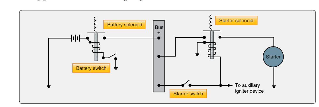
Because a starter motor can draw very high current during cranking — the exact figure varies significantly with engine size and starter design, so always consult the applicable maintenance manual for expected values — the circuit must use heavy-gauge cables and a remotely mounted starter solenoid (contactor) to handle the high current with a low-current control signal from the cockpit switch. When the pilot energizes the start switch, a small control current flows through the solenoid coil, pulling a plunger that physically closes heavy copper contacts. Those contacts complete the high-current circuit from the battery (or ground power unit) directly to the starter motor terminals. The solenoid also prevents the need to run heavy-gauge wire all the way to the instrument panel — a significant weight and safety advantage.
The master switch (battery and alternator switches) must be ON, the battery must be adequately charged, and all cable connections must be tight and corrosion-free. A healthy battery under starter cranking load will sag somewhat from its resting voltage but should not drop excessively — consult the aircraft and battery manufacturer's specific minimum acceptable cranking voltage for the system voltage installed (nominally 12 V or 24 V systems). Voltage drop across the starter circuit is one of the most important diagnostic parameters a technician can measure.
Why It Matters — Safety and Airworthiness
A direct-cranking starter that malfunctions can cause far more than an inability to start the engine. A starter that remains engaged after the engine fires will be over-driven by the now-running engine, potentially destroying the Bendix drive, damaging the ring gear, and — in extreme cases — causing the starter to disintegrate. A seized or shorted starter can drain the aircraft battery completely and, if the solenoid sticks closed, generate enough heat to start an electrical fire. Conversely, an intermittent open in the brush circuit can cause hard-starts that pilots may try to overcome with excessively long cranking cycles, overheating the motor and warping the armature. Under 14 CFR Part 43, any repair or overhaul of a starter must comply with the manufacturer's maintenance manual and, where applicable, the component's approved data.
Key Numbers and Rules
- Maximum continuous cranking time: Most manufacturers limit individual cranking attempts to 30 seconds or less, followed by a cooling period (often 1–2 minutes) before the next attempt. Always consult the aircraft's Pilot Operating Handbook (POH) or Aircraft Flight Manual (AFM) and the engine maintenance manual for the specific limit.
- Brush wear limit: Carbon brushes are typically replaced when worn to half their original length or to the minimum length specified in the overhaul manual — whichever occurs first. Worn brushes cause arcing, accelerated commutator wear, and reduced cranking torque.
- Commutator undercutting: After resurfacing (turning) the commutator in a lathe, the mica insulation between segments must be undercut to approximately 1/32 inch (about 0.031 inch) below the copper surface so brushes make full contact with the copper. Failure to undercut causes rapid brush wear.
- Voltage drop limit: FAA-H-8083-32 does not specify a single universal voltage drop figure for all installations; acceptable voltage drop across the starter circuit (cables, solenoid contacts, connections) is set by the airframe and component manufacturer, often expressed as a percentage of system voltage or a maximum drop per component. Excessive drop starves the motor and causes hard-starting without any fault in the starter itself.
- Insulation resistance: An armature or field winding should show very high resistance (typically greater than 1 megohm) to ground when tested with a megohm meter; low insulation resistance indicates moisture ingress or winding breakdown.
- Starter solenoid contact resistance: Closed contacts should show near-zero resistance. Pitted or burned contacts dramatically increase voltage drop and reduce available cranking torque.
Troubleshooting Direct-Cranking Electric Starters
Effective troubleshooting follows a logical, divide-and-conquer approach — isolate whether the problem is in the electrical supply, the control circuit, the solenoid, or the starter motor itself before replacing any component.
No-crank condition (starter does not turn at all): First verify battery voltage and state of charge with a load test. Check the master switch, starter switch, and all fuses or circuit breakers in the control circuit. Using a multimeter, confirm voltage is present at the solenoid control terminal when the start switch is activated. If the solenoid clicks but the starter does not crank, check for voltage at the starter motor terminal with the solenoid energized. No voltage at the motor terminal with voltage at the solenoid input indicates a failed solenoid (open or burned contacts). Voltage present at the motor terminal but no rotation indicates a failed starter (open armature winding, seized bearings, or worn brushes not making contact).
Slow cranking: This is almost always an electrical issue first — discharged battery, excessive resistance in cables or connections, or corroded solenoid contacts. Perform a voltage drop test across each segment of the circuit while cranking and compare readings to the manufacturer's specified limits for that segment. If the circuit checks out, the starter itself may have shorted turns in the armature (low resistance between windings), which reduces back-EMF and causes the motor to draw excessive current while producing low torque.
Starter does not disengage: If the starter continues to run after the engine fires (heard as a high-pitched whine from the starter), release the start switch immediately. The fault is either a stuck solenoid (contacts welded closed) or a Bendix drive that has failed to retract. Inspect the Bendix drive for corrosion, debris, or a broken spring. A stuck solenoid requires solenoid replacement. Prolonged engagement will destroy the drive and may damage the ring gear.
Starter engages with grinding noise: This typically indicates the Bendix drive pinion is not meshing cleanly — either the pinion teeth or the ring gear teeth are worn, chipped, or misaligned. Inspect both the drive pinion and the starter adapter or ring gear for damage. A worn or improperly lubricated Bendix drive mechanism is a common cause.
Excessive arcing or burning smell: Arcing at the brushes (visible through ventilation holes) indicates worn brushes, a rough or out-of-round commutator, or high mica insulation. Remove the starter, inspect the commutator surface, measure brush length, and check insulation resistance with a megohm meter. A shorted armature winding, identifiable by a growler test during overhaul, will also cause heavy arcing and rapid overheating.
Common Test Traps
- Confusing starter types: The FAA written test for AMT Powerplant may ask you to distinguish a direct-cranking starter from an inertia starter. Remember — direct cranking applies torque immediately and continuously; an inertia starter spins up a flywheel first.
- Mica undercutting direction: Students often think you undercut mica flush with the copper. You must cut it below the copper surface so brushes ride on copper only, not on mica ridges.
- Slow cranking blame: A common trap is blaming the starter motor first. The majority of slow-cranking complaints are caused by a weak battery or high-resistance connections, not a faulty starter. Always test the circuit before pulling the starter.
- Series-wound motor behavior: A series-wound motor run with no load (such as a Bendix that fails to engage) will accelerate to destructive speeds. This is a testable characteristic — know why series motors must always have a mechanical load.
- Maximum cranking time limits: Exceeding the manufacturer's cranking time limit is a common maintenance error. Extended cranking overheats the armature windings and can warp the commutator. Always observe cooling intervals between start attempts.