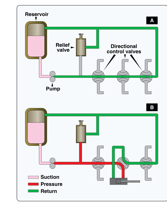
Hydraulic systems are the muscle behind many of the most critical functions on modern aircraft — landing gear extension and retraction, flight control actuation, brake application, and cargo door operation, among others. Yet not all hydraulic systems are built the same way. Two fundamental design philosophies govern how a hydraulic circuit manages fluid flow when the actuators it serves are not actively doing work: the open-center system and the closed-center system. Understanding the difference between these two architectures is essential for any aviation maintenance technician, because each design dictates the type of pump used, how pressure is regulated, how multiple subsystems share a single fluid source, and what failure modes to anticipate.
Both systems use the same basic components — a reservoir, a pump, lines and fittings, control valves, actuating cylinders, and a return path — but the philosophy of fluid management at rest is where they diverge completely. Mastering this distinction is a cornerstone topic in the FAA Aviation Maintenance Technician Airframe certification curriculum.
How Open-Center Systems Work
In an open-center hydraulic system, fluid flows continuously through the system even when no actuator is being operated. The selector valves that control individual actuators are designed with an open center passage — meaning that in their neutral (unactuated) position, they allow fluid to flow straight through and return to the reservoir without doing any work. The pump is always moving fluid, and that fluid is always circulating.
Because fluid is always flowing, the pump used in an open-center system is typically a constant-displacement (fixed-displacement) pump — most commonly a gear pump or a simple vane pump. This type of pump delivers the same volume of fluid per revolution regardless of system demand. When no actuator is calling for work, the pump simply circulates fluid at low pressure through the open-center passages back to the reservoir. Pressure only builds in the system when a selector valve is moved to direct fluid against a load.
Open-center systems are typically arranged in series: multiple selector valves are plumbed one after another in a single circuit, so fluid flows through the center of the first valve, then the center of the second, and so on back to the reservoir. This design is simple and inexpensive. However, a key limitation is that only one actuator can be operated effectively at a time. If two valves are shifted simultaneously in a series circuit, the pressure is split between them, reducing the force available to each.
Another consequence of constant circulation is that the fluid absorbs heat continuously as it passes through lines and valves. Heat management and adequate reservoir sizing are therefore important maintenance considerations in open-center designs. Gear pumps in these systems are also susceptible to wear because they run at full output continuously, rather than modulating output to match demand.
How Closed-Center Systems Work
In a closed-center hydraulic system, fluid does not flow continuously through the circuit when actuators are idle. The selector valves in this design are closed in their neutral position — they block flow in both the pressure and return directions, trapping fluid in place. Because fluid has nowhere to go when all valves are closed, the system must use a different strategy to manage pump output.
Closed-center systems typically employ one of two solutions. The most common on modern transport-category and high-performance aircraft is a variable-displacement pump (often a piston-type axial pump). This pump automatically reduces its output to near zero when system pressure reaches a set level — called the compensator setting — and ramps back up when pressure drops due to actuator demand. The pump is always spinning (driven by the engine or an electric motor), but it stops delivering appreciable fluid once the system is pressurized and at rest. This makes the variable-displacement pump extremely energy-efficient and well-suited to aircraft that need continuous hydraulic readiness across multiple subsystems.
The second approach uses a constant-displacement pump combined with an unloading valve and an accumulator. When system pressure reaches the desired level, the unloading valve opens and bypasses pump output back to the reservoir at low pressure, effectively taking the load off the pump. The accumulator — a chamber divided by a piston or bladder that stores fluid under gas pressure — maintains system pressure during the unloaded period. When system pressure drops below a set threshold, the unloading valve closes and the pump recharges the accumulator. This arrangement mimics the behavior of a variable-displacement system while using simpler, less expensive pump hardware.
Because all selector valves in a closed-center system are closed in neutral, multiple actuators can share the same pressure source without fighting each other. Subsystems are typically plumbed in parallel: each selector valve taps off the common pressure manifold independently. When one actuator is working, it draws from the common pressurized supply; another actuator can be operated at the same time from the same supply with minimal interference, as long as the pump and accumulator can meet the combined demand. Closed-center designs are common on many transport-category aircraft with numerous hydraulic subsystems, though some large aircraft have historically used open-center hydraulic systems, so the choice of architecture depends on the specific design rather than aircraft size alone.
Why It Matters
The choice between open-center and closed-center architecture has direct consequences for safety, reliability, and maintenance practice. A closed-center system with a variable-displacement pump is inherently pressurized and ready to act the instant a valve is shifted, with no lag time for pressure to build. This rapid response is critical for flight control surfaces and emergency braking on fast aircraft. An open-center system, by contrast, builds pressure only on demand, introducing a slight delay and making it unsuitable for applications requiring instantaneous high-force response.
From a maintenance standpoint, understanding which type of system you are working on determines proper troubleshooting technique. In an open-center system, if the pump is running, fluid should be flowing; a pressure gauge showing zero while the pump runs indicates a severe internal leak or open-center valve failure. In a closed-center system, high static pressure with the pump running normally at idle is expected behavior — it means the system is holding pressure correctly. Misunderstanding this can lead to false diagnoses.
Fluid contamination and overheating are also affected by system type. Closed-center systems circulate fluid far less when at rest, so fluid temperatures tend to be lower during idle periods but can spike quickly under heavy cyclic demand. Open-center systems run fluid continuously, generating a steady heat load but distributing it more evenly over time.
Key Numbers and Rules
- Open-center selector valves allow fluid to pass through in neutral; closed-center selector valves block flow in neutral.
- Aircraft hydraulic system operating pressures vary considerably by design — many transport-category systems are standardized around 3,000 psi, with newer designs (such as the Boeing 787) operating at 5,000 psi, while light aircraft open-center systems commonly operate at lower pressures; exact figures depend on the specific aircraft and system design.
- Variable-displacement pumps used in closed-center systems reduce their stroke (displacement per revolution) automatically when the compensator pressure is reached, reducing flow output to near zero.
- Accumulators in closed-center systems serve multiple functions: dampening pressure surges, maintaining pressure during brief pump unloading, and providing an emergency reserve of pressurized fluid.
- Series vs. parallel plumbing: open-center systems favor series arrangements (one actuator at a time); closed-center systems use parallel arrangements (multiple actuators independently served from a common pressure source).
- A constant-displacement pump in an open-center system runs at full output continuously; its wear rate is higher than a variable-displacement pump operating at reduced output most of the time.
- Gear pumps are the most common pump type in open-center systems; piston pumps (axial or radial) are the most common in closed-center systems due to their ability to vary displacement.
Common Test Traps
- Confusing valve behavior with fluid behavior. The FAA knowledge test often asks what happens to fluid flow in the neutral position. Remember: open-center = fluid flows through the valve and returns to reservoir; closed-center = fluid is blocked in both directions at the valve.
- Assuming high pressure always means something is wrong. In a closed-center system, static pressure at or near the system operating pressure is normal and expected when no actuators are working. Students trained on open-center systems sometimes flag this incorrectly as a fault.
- Mixing up pump types. Constant-displacement pumps go with open-center systems (fluid always circulates). Variable-displacement pumps go with closed-center systems (output modulates to hold system pressure). Confusing these on the test is a common error.
- Overlooking the accumulator's role. Questions may ask why a closed-center system uses an accumulator. It is not just for emergency backup — it also maintains pressure during the pump's unloading cycle and absorbs pressure spikes that could damage system components.
- Misidentifying which design allows simultaneous actuator operation. Open-center series systems can only operate one actuator effectively at a time. Closed-center parallel systems can operate multiple actuators simultaneously from the common pressurized manifold. The FAA tests this distinction directly.