Hydraulic systems are the muscle behind many of an aircraft's most critical functions — retracting the landing gear, actuating flight control surfaces, powering brakes, and operating thrust reversers. At the heart of every hydraulic system is the pressure-generation side: the pumps that convert mechanical or electrical energy into a continuous flow of pressurized fluid. For the aviation maintenance technician (AMT) working on airframes, a thorough understanding of how hydraulic pressure is generated, what types of pumps accomplish that task, and how each behaves under normal and abnormal conditions is not just a knowledge-test requirement — it is a fundamental safety competency.
This article covers the operating principles of each major hydraulic pump type found on certificated aircraft, the design features that distinguish them, their typical applications, and the maintenance and troubleshooting considerations that arise in practice. All concepts are grounded in FAA guidance for airframe hydraulic and pneumatic systems.
How Hydraulic Pressure Is Generated
Hydraulic pressure is produced by resisting the flow of an incompressible fluid. A pump moves fluid from a reservoir into a closed circuit; downstream actuators and valves resist that flow, and the resulting pressure differential does the work. The fundamental relationship is straightforward: a pump creates flow, and the system's resistance to that flow creates pressure. No downstream resistance means no pressure buildup — a critical concept when diagnosing pump and system faults.
Aircraft hydraulic systems typically operate at one of several standardized pressure ranges. Older general aviation and light transport aircraft often use systems in the 1,000–1,500 psi range, while many transport-category aircraft operate at 3,000 psi. A number of newer transport-category designs, including some current-production widebody aircraft, operate at 5,000 psi to reduce the size and weight of components. The AMT must always consult the aircraft maintenance manual (AMM) for the specific system pressure before performing any work or functional test.
Main Pump Types and How They Work
Engine-Driven Pumps (EDP)
The engine-driven pump is the primary pressure source on most multi-engine transport and many general aviation aircraft. It is mechanically coupled — typically through an accessory gearbox pad — directly to an engine, so it operates whenever the engine runs. On transport-category aircraft, EDPs are commonly of the variable-displacement, axial-piston design, though many general aviation aircraft still use fixed-displacement gear or vane pumps.
In an axial-piston pump, a rotating cylinder block carries multiple pistons arranged parallel to the drive shaft. The pistons stroke in and out as the block rotates because they ride against an angled swashplate. The angle of the swashplate determines piston stroke length and therefore the volume of fluid displaced per revolution. In a variable-displacement pump, a compensator mechanism automatically changes the swashplate angle in response to system pressure. When system pressure reaches the desired level, the compensator reduces swashplate angle until the pump is nearly at zero displacement (on-stroke to off-stroke), dramatically reducing heat generation and drive-shaft load. This is why variable-displacement pumps are far more efficient than fixed-displacement designs for continuous aircraft use — they only work as hard as the system demands.
A fixed-displacement pump, by contrast, moves the same volume of fluid per revolution regardless of system pressure. To prevent dangerous over-pressurization, fixed-displacement installations require a pressure relief valve to return excess flow to the reservoir. Fixed-displacement gear pumps and vane pumps fall into this category and are more common on smaller aircraft or as auxiliary/backup sources.
Electric Motor-Driven Pumps (EMDP or EMP)
Electric motor-driven pumps use an AC or DC electric motor to drive a hydraulic pump element — most often an axial-piston unit similar in design to an EDP, but smaller. EMDPs serve several important roles: they provide hydraulic power when engines are not running (during ground servicing or pre-flight checks), they act as backup or auxiliary pressure sources if an EDP fails, and on some aircraft they power a dedicated circuit such as the brake system independently of the main engine-driven supply.
Because electric pumps draw significant current, they are not intended for continuous high-demand operation on most designs. The AMT must be aware that running an EMDP for extended periods without adequate fluid cooling can overheat the motor and pump assembly. Some installations incorporate thermal protection devices that will shut the pump off automatically if overtemperature is detected.
Hand Pumps
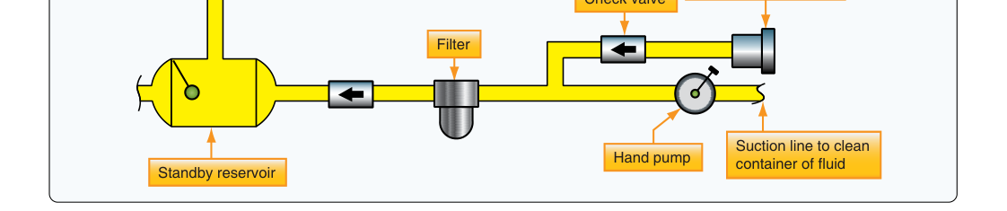
Hand pumps are human-powered, double-acting piston pumps that displace fluid on both the forward and return strokes, providing flow in both directions of handle travel. They are typically found as emergency or backup sources for systems such as landing gear extension, brake application, or flight control unlocking on smaller aircraft. A hand pump will raise system pressure to the level needed to operate a specific actuator, but the flow rate is low — the pilot or technician must pump repeatedly to move an actuator through its full travel.
Double-acting design is important: check valves on each side of the piston allow fluid to be drawn from the reservoir on one stroke and pushed into the pressure line on the other, so no stroke is wasted. Hand pumps are simple, reliable, and require no external power source, making them ideal emergency backups.
Air-Driven Pumps and Power Transfer Units
Some aircraft use air-driven pumps (ADPs), a less common pump type that uses engine bleed air or a dedicated pneumatic source to spin a turbine that drives a hydraulic pump. ADPs allow one engine's bleed air to power a hydraulic circuit normally fed by a different engine's EDP, adding redundancy without electrical load.
A power transfer unit (PTU) is not a pump in the traditional sense but deserves mention here because it transfers hydraulic power between two independent systems without transferring fluid between them. A hydraulic motor on one system drives a hydraulic pump on the other; fluid stays segregated, maintaining system separation and preventing cross-contamination.
Why It Matters: Safety and Redundancy
Hydraulic system failure can render critical flight controls, brakes, and gear inoperative. This is why regulations and aircraft designs mandate redundancy — typically two or three independent hydraulic systems, each with its own pump sources, fluid reservoir, and lines. Understanding pump types helps the AMT verify that each redundant source is fully functional and that backup pumps will take over if the primary EDP fails. A malfunctioning compensator that keeps an EDP at full displacement even at high system pressure, for example, will continuously generate heat, overheat the fluid, and eventually damage seals and actuators throughout the system.
Hydraulic fluid contamination is another critical concern. Pumps are precision components with very tight internal clearances; even small particles can score pump barrels and pistons, generating more metal particles that cascade through the system. Regular fluid sampling and filter servicing are directly tied to pump longevity.
Key Numbers and Rules
- Typical system pressures: Light GA aircraft — 1,000–1,500 psi; many transport-category aircraft — 3,000 psi; some transport-category designs — 5,000 psi.
- Variable-displacement pump operation: When system pressure reaches the compensator set point, swashplate angle decreases to near zero displacement, reducing load and heat.
- Fixed-displacement pumps require pressure relief valves to prevent over-pressurization because output volume per revolution is constant.
- Hand pumps are double-acting — they produce flow on both the push and pull strokes via check valves.
- EMDPs are designed for intermittent, not continuous, operation in most installations; thermal protection devices may automatically shut them down.
- PTUs transfer power between hydraulic systems without mixing fluid — each system retains its own fluid supply.
- Always consult the Aircraft Maintenance Manual (AMM) for system-specific pressure specifications before any test or servicing operation.
Common Test Traps
- Confusing flow with pressure: Pumps create flow; pressure is a result of resistance to that flow. A pump running against no resistance produces flow but little pressure — this distinction is frequently tested.
- Variable vs. fixed displacement: Assuming all piston pumps are variable-displacement. Gear pumps and vane pumps are fixed-displacement and always need relief valves. Knowing which type serves as the primary pump on a given aircraft type is important.
- Hand pump stroke direction: Some students assume a hand pump only delivers on the forward (push) stroke. It is double-acting — fluid is delivered on both strokes.
- EMDP continuous operation: The exam may describe a scenario where an EMDP is run for an extended period and ask about consequences. Overheating and thermal shutoff — not simply low pressure — is the expected outcome.
- PTU fluid transfer misconception: A PTU does NOT transfer hydraulic fluid between systems. It transfers power through a motor-pump coupling while each system keeps its own fluid. Confusing a PTU with a cross-feed valve is a common error.