What Is a Constant-Speed Propeller?
Most high-performance and complex aircraft are equipped with a constant-speed propeller — a variable-pitch propeller whose blade angle is automatically adjusted to maintain a pilot-selected RPM regardless of changes in airspeed or engine power. Unlike a fixed-pitch propeller, which produces a single blade angle that can only be optimal for one flight condition, the constant-speed system allows the engine to operate at its most efficient RPM across climb, cruise, and descent. The device that makes this possible is the propeller governor.
How the Governor Works: The Core Mechanism
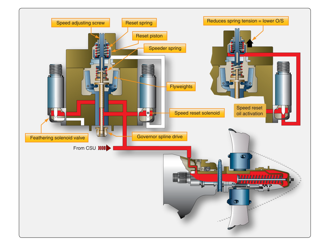
The propeller governor is a hydromechanical device driven by the engine — typically at a fixed ratio to crankshaft speed through the accessory gearing. Its job is to sense actual engine RPM, compare it to the pilot-selected RPM, and then direct engine oil under pressure to a piston inside the propeller hub to change blade pitch accordingly. Understanding the three states of operation — on-speed, underspeed, and overspeed — is essential for the commercial knowledge test and for safe operation.
The Flyweight Assembly
At the heart of the governor is a set of flyweights mounted on a rotating shaft. As engine RPM increases, centrifugal force throws the flyweights outward. As RPM decreases, spring tension pulls them inward. The flyweights act on a pilot valve (also called a speeder valve or spool valve) — a small sliding valve that controls whether oil flows into the propeller piston, flows back to the engine sump, or is blocked. The position of this pilot valve is the key to understanding all three governor states.
The Speeder Spring
Opposing the outward force of the flyweights is the speeder spring, which is compressed or relaxed by moving the propeller control lever in the cockpit. When the pilot moves the prop control forward (toward higher RPM), the speeder spring is compressed, requiring greater flyweight force — and thus higher RPM — to move the pilot valve. Moving the prop control aft reduces spring tension, allowing the flyweights to move the pilot valve at lower RPM. In this way, the pilot sets the reference RPM by adjusting speeder spring tension, and the governor automatically maintains it.
The Three States of Governor Operation
On-Speed Condition
When the engine is running exactly at the selected RPM, flyweight centrifugal force perfectly balances speeder spring force. The pilot valve rests in a neutral (lapped) position, and oil neither enters nor exits the propeller piston. Blade pitch remains constant. This is the normal, steady-state condition during stable cruise flight.
Underspeed Condition
If engine RPM drops below the selected value — for example, if the pilot reduces the throttle or the aircraft climbs into thinner air — flyweight centrifugal force decreases and the speeder spring pushes the pilot valve downward (in most designs). This opens a port that allows high-pressure engine oil to flow to the propeller piston, which drives the blades toward a lower (finer) pitch. A lower pitch angle reduces the aerodynamic load on the propeller, allowing the engine to accelerate back to the selected RPM. Once the target RPM is restored, the flyweights return to their balanced position and oil flow stops.
Overspeed Condition
If engine RPM rises above the selected value — as happens when the pilot advances the throttle or enters a descent that increases propeller airspeed — flyweight centrifugal force overcomes the speeder spring and pushes the pilot valve upward. This opens a port that allows oil to drain back to the sump from the propeller piston, and the blades move toward a higher (coarser) pitch. Greater blade pitch angle means more aerodynamic load, which slows the propeller back to the selected RPM. Again, when equilibrium is reached, oil flow stops.
Oil Pressure and the Fail-Safe Design
It is critically important to understand the direction of oil pressure action. In most single-engine aircraft with a constant-speed propeller, oil pressure drives the blades toward low pitch (high RPM), while counterweights and/or propeller blade springs drive blades toward high pitch (low RPM) when oil pressure is removed. This means that in the event of an oil pressure failure — a broken oil line, failed governor, or engine failure — the propeller will automatically move to high pitch (coarse), which in a power-off situation reduces propeller drag and windmilling loads. This is a deliberate, built-in safety feature.
Some multi-engine aircraft use full-feathering propellers, where a separate accumulator or spring system drives the blades all the way to the feathered position (approximately 90° blade angle) upon loss of oil pressure. In most such systems, oil pressure opposes the feathering springs/counterweights and holds the blades out of feather during normal operation, though system designs vary. Feathering minimizes drag after an engine failure, which is critical for multi-engine performance and control.
Propeller Control in the Cockpit
In aircraft equipped with both a throttle and a propeller control (blue knob), the pilot manages power with two inputs. The throttle controls manifold pressure (the amount of air/fuel mixture entering the engine), while the propeller control sets the governor's target RPM. The combination of manifold pressure and RPM determines the actual power output of the engine.
A fundamental operating rule is: when increasing power, increase RPM first, then manifold pressure; when decreasing power, reduce manifold pressure first, then RPM. This sequence prevents a condition called overboosting — running high manifold pressure at low RPM — which can cause excessive cylinder pressures and potential engine damage. For example, a common limit in many training aircraft is to avoid running manifold pressure (in inches Hg) numerically higher than RPM (in hundreds). Always consult the specific Pilot's Operating Handbook (POH) for limits.
RPM, Manifold Pressure, and Power Management
Understanding that the governor decouples RPM from throttle position is key. Once the governor is engaged (engine RPM at or above the governor's set point), advancing the throttle alone does not increase RPM — it increases manifold pressure and torque. The governor responds to the momentary overspeed tendency by coarsening pitch, absorbing the extra power as increased thrust rather than higher RPM. This is why the tachometer stays nearly constant during throttle changes during normal cruise — the governor is actively compensating.
Conversely, during a descent at a fixed throttle setting, as airspeed builds and the propeller tends to speed up (like a windmill), the governor coarsens pitch to hold RPM steady. The pilot will also notice increased manifold pressure in a descent even without touching the throttle — this is primarily because ambient (atmospheric) pressure increases as altitude decreases, which raises manifold pressure at a fixed throttle setting.
Practical Considerations for the Commercial Pilot
- Run-up checks: During the preflight engine run-up, the propeller system is exercised by momentarily moving the prop control from high RPM to a lower setting and back. This circulates fresh, warm oil into the governor and propeller hub, and verifies governor response. Each cycle should produce a distinct and predictable RPM drop.
- Cold oil: In cold weather, thick oil may not flow properly to the propeller hub. Prop cycles during run-up warm the oil. Always allow proper warm-up before cycling the prop rapidly.
- Propeller limits: Never exceed the maximum RPM placard limits. Over-speed events stress propeller hubs, blades, and engine crankshaft flanges. A maintenance inspection may be required after an overspeed event.
- Low-pitch stops: Governors incorporate a low-pitch stop — a mechanical limit preventing blades from going flat or below a minimum angle, which would cause the engine to overspeed uncontrollably.
Memory Aid
To remember oil pressure action: