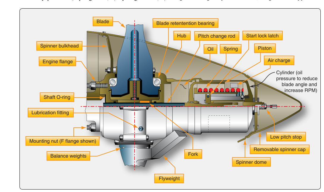
One of the most elegant pieces of hydromechanical engineering aboard a piston-powered aircraft is the constant-speed propeller governor. Unlike a fixed-pitch propeller — where blade angle is fixed and RPM swings wildly with airspeed and power changes — a constant-speed propeller system continuously adjusts blade pitch to hold a pilot-selected RPM. Understanding how the governor achieves this, and how to maintain or troubleshoot it, is central to the FAA Aviation Mechanic Powerplant curriculum.
The system exists because an engine produces maximum power only within a narrow RPM band. By keeping the engine on that peak, a constant-speed propeller extracts the most thrust for a given throttle setting, making the aircraft more efficient at climb, cruise, and descent. The governor is the brain of the system, translating pilot intent (via the propeller control lever) into precise, real-time hydraulic commands.
Basic Components of the System
A constant-speed propeller system has three main elements working together: the governor, the pitch-change mechanism inside the propeller hub, and the propeller control in the cockpit. Counterweights, springs, or hydraulic pistons inside the hub provide the force to change blade angle, while the governor directs engine oil — at elevated pressure — to assist or oppose those forces.
Most light aircraft use a single-acting hydraulic system. Engine oil, boosted to a higher pressure by a pump inside the governor body, is directed to or away from a hydraulic piston in the hub. In the most common configuration, oil pressure drives the blades toward low pitch (high RPM), while centrifugal twisting moment and counterweights drive the blades toward high pitch (low RPM) when oil is released. Some turboprop and large reciprocating engines use double-acting systems with oil pressure on both sides of the piston, but the governing principle is the same.
How the Governor Works: The Flyweight Mechanism
The heart of the governor is a set of rotating flyweights mounted on a spinning drive gear that is turned by the engine (typically at a fixed ratio to crankshaft speed). Centrifugal force pushes the flyweights outward as RPM increases, and spring tension pulls them inward as RPM decreases. The balance between flyweight force and spring tension determines a speeder spring load — and that load is precisely what the pilot sets with the propeller control lever.
The flyweights are mechanically linked to a pilot valve (sometimes called a spool valve). This valve slides up or down based on flyweight position, opening or blocking oil ports to the propeller hub. Three distinct conditions govern the valve's behavior:
- On-speed condition: Flyweight force exactly equals speeder spring force. The pilot valve is centered, oil ports are blocked, and blade pitch does not change. The propeller maintains the selected RPM.
- Overspeed condition: RPM rises above the selected value. Flyweights fly outward, lifting the pilot valve and opening a port that allows pressurized oil to flow toward low pitch — but wait. In most systems, the valve actually dumps oil back to the sump, reducing hub pressure and allowing counterweights and the twisting moment to drive the blades to high pitch (increased angle). High pitch adds load to the engine, slowing it back to the governed speed.
- Underspeed condition: RPM falls below the selected value. Flyweights move inward, the pilot valve drops, and the governor routes boosted oil pressure to the hub, driving the blades toward low pitch. Low pitch reduces the load on the engine, allowing it to accelerate back to the governed RPM.
This feedback loop is continuous and rapid. The governor responds to deviations in fractions of a second, keeping RPM variation extremely small — typically within a few RPM of the selected value during stable flight.
The Speeder Spring and Propeller Control Lever
The speeder spring is the key to pilot authority over the system. Moving the propeller control lever forward increases the compression load on the speeder spring, requiring greater flyweight force — and therefore higher RPM — to reach the on-speed condition. Moving the lever aft reduces spring tension, allowing the flyweights to reach equilibrium at a lower RPM. In this way, the pilot can select any RPM within the governor's operating range, usually from just below idle to the engine's rated maximum.
It is critical for mechanics and pilots alike to understand that the throttle and propeller control levers operate independently. The throttle sets manifold pressure (fuel-air mixture and thus power output). The propeller control sets the governor's target RPM. The engine will develop whatever power corresponds to the manifold pressure setting — the governor's only job is to load or unload the propeller to maintain the chosen RPM, not to control power directly.
Oil Pressure and the Feathering System
In most single-engine aircraft, if the governor loses oil pressure — due to an engine failure or a broken oil line — the propeller will move toward high pitch (low RPM) because the counterweights and aerodynamic twisting moment are no longer opposed by oil pressure. This is called a fail-safe to high pitch design. In a multi-engine aircraft fitted with a feathering propeller, this logic is extended: if oil pressure drops to zero, the blades can be driven all the way to the feather position (approximately 90° pitch), stopping rotation entirely to minimize drag after an engine failure.
Feathering is normally accomplished by routing engine oil, boosted by an engine-driven or electric auxiliary oil pump, to the propeller hub to drive the blades to the feather position — not by a dedicated nitrogen supply. Some designs incorporate a feathering accumulator, a reservoir that stores engine oil under pressure (charged on the air side with compressed air or nitrogen, though the fluid delivered to the propeller is oil). The accumulator's primary purpose is to assist unfeathering — pushing stored oil to the hub to bring the blades out of feather so the engine can be windmilled for an airstart — rather than serving as the main source of feathering pressure. The governor on a feathering system includes a feathering valve and a high-pitch stop that can be bypassed when the cockpit feathering control is selected.
Governor Inspection and Maintenance
The FAA Aviation Mechanic Powerplant Handbook (FAA-H-8083-31) outlines the maintenance technician's responsibilities regarding governors. Key maintenance tasks include:
- Oil leakage inspection: Seals and O-rings inside the governor body deteriorate with age and heat. Any external oil seepage around the governor base or pilot valve area requires immediate investigation.
- Drive coupling check: The governor drive gear must be in good condition. Worn splines cause imprecise RPM control and can result in governor failure.
- Adjustment and calibration: After overhaul or replacement, the governor must be set to the correct maximum RPM using a tachometer and, where applicable, a dedicated test stand. The adjustment screw on the governor body changes speeder spring preload and must be set to the manufacturer's specification.
- Relief valve pressure check: The governor contains an internal relief valve to limit boost pressure. Incorrect pressure — too high or too low — causes erratic pitch changes or loss of authority.
- Logbook entries: Any governor removal, installation, or adjustment requires an appropriate maintenance record entry per 14 CFR Part 43.
Why It Matters: Safety and Performance
A malfunctioning governor can manifest in several serious ways in flight. A stuck pilot valve may cause the propeller to run at a fixed pitch, functionally degrading the aircraft to fixed-pitch performance with a possible RPM exceedance. A governor that hunts (continuously oscillating RPM) suggests worn flyweight bearings, contaminated oil, or an incorrect speeder spring load. An inability to feather a failed engine on a multi-engine aircraft dramatically increases the difficulty of controlling the aircraft and must be considered an emergency.
From a powerplant examiner's perspective, understanding the governor is also essential because it sits at the intersection of engine operation, propeller certification, and hydraulic systems — three major AMT knowledge areas that appear throughout the Powerplant written and oral examinations.
Key Numbers and Rules
- Governor drive ratios vary by engine but are always a fixed, known ratio to crankshaft speed — verify the correct ratio in the engine or governor manual before installation.
- Boosted oil pressure in a typical light-aircraft governor ranges from approximately 200 to 300 psi, well above the engine's normal oil pressure of 60–90 psi.
- Feathering propeller blade angles are typically 85° to 90° from the plane of rotation.
- All governor overhauls are performed at the interval specified in the manufacturer's Instructions for Continued Airworthiness (ICA), often concurrent with engine overhaul.
- Maintenance on a constant-speed propeller system is classified as a major alteration or major repair if it involves internal governor components — requiring an FAA Form 337 or return to an appropriately rated facility per 14 CFR Part 43, Appendix A.
Common Test Traps
- High pitch vs. low pitch confusion: Remember that high pitch = high blade angle = low RPM = high load. When the governor corrects an overspeed, it moves the blades to high pitch, not low pitch. Mixing these up is the most common error on written exams.
- Oil pressure direction: In a single-acting system, oil pressure typically drives blades toward low pitch, while spring/counterweight force drives toward high pitch. A loss of oil pressure therefore moves blades toward high pitch — not low pitch as students often guess.
- Throttle vs. propeller control independence: The propeller control sets RPM; the throttle sets manifold pressure. Students frequently confuse the two when answering questions about power management.
- On-speed is not zero movement: On-speed means the pilot valve is centered and pitch is momentarily stable — not that the propeller has stopped adjusting forever. Any change in airspeed or power will create a new overspeed or underspeed condition requiring correction.
- Feathering accumulator purpose: Some students believe the accumulator is for normal pitch changes. It is specifically for storing oil under pressure to assist unfeathering (restarting a windmilling engine) — an important emergency function, not the primary means of feathering.