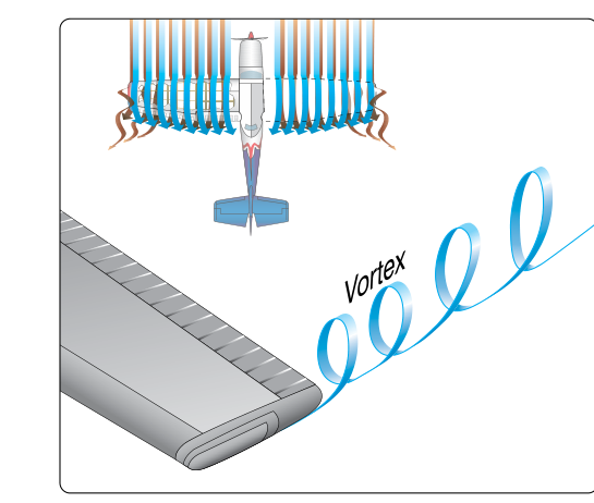
Every wing that generates lift pays a hidden aerodynamic tax. The same pressure difference that pushes an airplane skyward also drives air sideways across the span, rolls it into spiraling columns at each wingtip, and bends the local airflow in a way that steals energy from the aircraft. Understanding this chain of events—from spanwise flow to wingtip vortices to induced drag—is essential for any flight or ground instructor because it underlies stall behavior, wake turbulence hazards, best-glide performance, and the physics behind high-aspect-ratio wing design. The FAA's Pilot's Handbook of Aeronautical Knowledge (PHAK, FAA-H-8083-25) treats this as foundational aerodynamics, and the Airman Certification Standards test it at both the private and instrument levels.
How Spanwise Flow Originates
A wing in flight creates lift by maintaining lower pressure on the upper surface and higher pressure on the lower surface. This pressure gradient acts not only perpendicular to the wing—pushing it upward—but also parallel to it, from root to tip and from tip to root, depending on which surface you examine. On the lower (high-pressure) surface, air is pushed outward toward the wingtip. On the upper (low-pressure) surface, air is drawn inward toward the fuselage. The result is that airflow across both surfaces has a spanwise component superimposed on its normal chordwise direction.
This spanwise drift is not a design defect; it is a physical inevitability for any wing of finite span that generates lift. The only way to eliminate it entirely would be to have an infinitely long wing—an abstraction called an infinite wing or two-dimensional airfoil that exists only in wind-tunnel theory. Real wings are finite, so spanwise flow always exists wherever a pressure differential exists across the span.
How Wingtip Vortices Form
The two opposing spanwise flows—outward below, inward above—converge at the trailing edge and especially at the wingtip, where air from the high-pressure underside spills around the tip to the low-pressure upper surface. This continuous spillage wraps into a tightly wound spiral. Behind each wingtip, a discrete vortex forms and trails aft as a rotating tube of air. Viewed from directly behind the aircraft, the right wingtip vortex rotates clockwise and the left wingtip vortex rotates counterclockwise. Between the two vortex cores the air moves downward; outboard of each tip the air curls upward. This downward motion between the tips is called downwash, and it is the direct cause of induced drag.
Vortex intensity depends on two variables above all others: lift being generated and airspeed. A heavy aircraft flying slowly—a transport category jet on final approach, for example—is generating maximum lift at a high angle of attack and produces the strongest, most dangerous vortices. The PHAK confirms this relationship, and the AIM dedicates an entire section to wake turbulence avoidance based on these aerodynamic principles.
From Vortices to Induced Drag: The Mechanism
The downwash produced by the vortex system does not stay neatly behind the wing—it influences the airflow at the wing itself. The effective angle of attack that the wing actually experiences is slightly less than the geometric angle of attack set by the pilot, because the downwash tilts the local relative wind slightly downward. Since lift is defined as the force acting perpendicular to the local relative wind (not the free-stream), this downward tilt rotates the total lift vector slightly rearward. That rearward component—a portion of what would otherwise be pure lift—now opposes the direction of flight. This is induced drag: drag literally induced by, and inseparable from, the production of lift.
A useful way to visualize this for students: imagine the wing trying to pull itself forward and upward, but the downwash leans the lift vector back just enough to create a rearward-acting force. No lift, no downwash, no induced drag. This is why induced drag is sometimes called drag due to lift.
The Airspeed Relationship and the Drag Curve
Induced drag has a precise and testable relationship with airspeed. Because a slower aircraft must fly at a higher angle of attack to generate the same lift, the pressure differential across the span is larger, spanwise flow is stronger, vortices are more intense, and downwash is greater. The result is that induced drag varies inversely with the square of true airspeed: halve the airspeed and induced drag quadruples. Conversely, at high airspeeds a wing flies at a small angle of attack, the pressure differential is modest, vortices are weaker, and induced drag is relatively small.
Parasite drag (skin friction, form drag, interference drag) behaves in the opposite way—it increases with the square of airspeed. Plotting both curves on the same graph produces the classic total drag curve. The point of minimum total drag is where induced drag and parasite drag are equal, and it corresponds to the airspeed for maximum lift-to-drag ratio (L/Dmax). This is the most aerodynamically efficient operating point and directly determines best-glide speed as well as maximum-range airspeed for a propeller-driven aircraft. The PHAK explains this relationship in the context of both performance planning and emergency procedures.
Design Strategies That Reduce Induced Drag
Because induced drag is rooted in the finite span and the resulting spanwise flow, designers use several strategies to minimize it:
- High aspect ratio wings: Increasing wingspan while keeping the same wing area raises the aspect ratio. Spanwise flow near the tips still exists, but it affects a smaller percentage of the total span, reducing the overall induced drag penalty. High-performance gliders routinely use aspect ratios above 30:1 for this reason.
- Winglets: Vertical or angled tip extensions interrupt the spanwise spillage, weaken the tip vortex, and reduce induced drag without the structural weight penalty of a longer straight wing. The aerodynamic effect is similar to extending span.
- Elliptical lift distribution: An elliptically shaped wing (or one twisted and tapered to approximate elliptical loading) distributes lift such that induced downwash is uniform across the span, which is the theoretical minimum induced drag condition for a given span and lift.
- Reduced wing loading: Flying lighter reduces the lift the wing must generate at any given speed, weakening vortices and lowering induced drag.
Operational Significance for Instructors
Instructors must connect this aerodynamic theory to real flight decisions. Induced drag explains why an airplane near a stall demands dramatically more power to hold altitude—not just because lift is near its maximum angle of attack limit, but because induced drag is at its peak and the thrust required to overcome it is enormous. It explains why best-glide speed (L/Dmax) is the correct airspeed after an engine failure: flying faster or slower both increase total drag and shorten the glide. And it underpins every wake turbulence avoidance decision: the AIM instructs pilots to expect the strongest vortices behind large, heavy aircraft flying slowly with flaps up—exactly the configuration that maximizes induced drag and vortex intensity.
- Wake turbulence sinks: Vortices descend at roughly 400–500 feet per minute and level off approximately 900 feet below the generating aircraft's flight path, according to AIM guidance. The two vortices also drift with the wind, a critical factor when landing behind a heavy aircraft in a crosswind.
- Rotation point hazard: Vortices begin at the point of rotation on takeoff. A following aircraft should rotate before that point and climb above the preceding aircraft's flight path.
- Three-minute rule: AIM recommends allowing at least three minutes (or the controller-specified interval) before takeoff or landing behind a large aircraft in no-wind or light-wind conditions.
Key Numbers and Rules
- Induced drag is inversely proportional to airspeed squared; parasite drag is directly proportional to airspeed squared.
- Minimum total drag (L/Dmax) occurs where induced drag equals parasite drag.
- Best-glide speed = L/Dmax airspeed (published in the POH/AFM).
- Vortex strength increases with higher gross weight, slower airspeed, and clean (no-flap) configuration.
- High aspect ratio reduces induced drag; low aspect ratio (short, wide wings) increases it.
Common Test Traps
- Induced drag increases as speed decreases—students sometimes reverse this, confusing it with parasite drag. Remember: slow flight = high induced drag.
- L/Dmax is minimum total drag, not minimum induced drag. Minimum induced drag alone would be at the highest possible airspeed, which is not practical or efficient.
- Vortex rotation direction: Right vortex rotates clockwise, left rotates counterclockwise when viewed from behind. The upward curl is outboard of each tip, the downward wash is between the tips.
- Winglets reduce induced drag by inhibiting spanwise flow and weakening tip vortices—they do not eliminate the pressure differential. They are an induced-drag reduction device, not a lift-increasing device per se.
- A heavier aircraft on approach always generates stronger vortices than a lighter one at the same speed—weight (and therefore required lift) is the dominant factor, not just configuration.
Memory aid
"Slow, heavy, clean = meanest vortices." Low airspeed forces a high angle of attack; high gross weight demands more lift; a clean (no-flap) configuration concentrates the pressure differential. All three factors maximize spanwise flow, vortex intensity, induced drag, and wake turbulence hazard simultaneously.