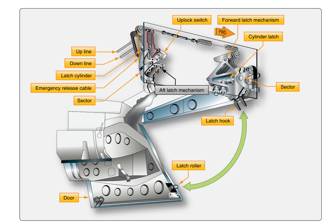
Every retractable landing gear system does more than simply fold the wheels into the airframe — it must also seal the wheel wells behind them. Wheel well doors serve the dual purpose of reducing aerodynamic drag in flight and protecting the gear bay from airstream contamination, ice accumulation, and structural stress. For the aviation maintenance technician (AMT) seeking airframe certification, understanding how these doors are actuated, sequenced, and rigged is as important as understanding the gear itself. A misrigged door can jam a gear leg mid-travel, fail to provide aerodynamic closure, or prevent the gear from extending in an emergency.
This article examines the types of wheel well doors found on certified aircraft, the mechanical and hydraulic systems that drive them, how sequencing is accomplished, and the maintenance and inspection considerations that appear on the FAA AMT Airframe knowledge test.
Types of Wheel Well Doors
Wheel well doors vary considerably in design depending on aircraft size, gear geometry, and manufacturer philosophy. The most common arrangements are:
- Full-closure doors: A set of doors completely encloses the wheel well after the gear retracts. The doors open first to allow gear travel, then close again once the gear is up and locked. On extension, they open again, the gear descends, and the doors may partially close around the gear leg once it is down and locked.
- Partial-closure or fairing doors: Some aircraft use smaller doors or gear-leg fairings that follow the gear leg through its travel. These fairings are mechanically linked directly to the gear strut so that as the gear moves, the fairing moves with it. No separate sequencing mechanism is needed for these panels, but alignment is critical.
- Open-well designs (no doors): Certain simpler retractable aircraft leave the wheel well partially open. A portion of the wheel and strut may remain exposed in flight. This design reduces mechanical complexity at the cost of some aerodynamic efficiency.
On larger transport-category and complex general aviation aircraft, the full-closure system is the norm because aerodynamic drag penalties of an open well at cruise speeds are unacceptable.
Actuation Mechanisms — How the Doors Move
Gear doors may be driven by several different actuator types. The choice depends on the aircraft's primary power system and the complexity of the installation.
Hydraulic Actuators
Most high-performance and transport-category aircraft use dedicated hydraulic actuators for door operation. Each door panel has its own linear actuator — essentially a hydraulic cylinder — mounted between the airframe structure and the door. When hydraulic pressure is directed to the actuator, the door swings open; when pressure is reversed or released, the door swings closed. Doors are typically held closed in flight by hydraulic pressure, by an over-center mechanical lock, or by a latch mechanism to prevent flutter or inadvertent opening. Pressure seals within these actuators are subject to wear and must be inspected per the manufacturer's maintenance manual and time limits.
Mechanical Linkage (Gear-Driven Doors)
On many general aviation retractable aircraft, the gear doors are driven entirely by mechanical linkage connected to the gear actuating mechanism itself. As the gear strut travels through its arc, a set of push-pull rods, bellcranks, and torque tubes simultaneously drive the door open and then, through a cam or over-center arrangement, pull it closed once the gear reaches the up-and-locked position. The critical advantage is simplicity — no separate sequencing valve is required. The disadvantage is that rigging tolerances are tight: if the linkage geometry is even slightly off, the door may not close flush, may bind against the gear leg, or may impose side loads on the gear structure itself.
Electric Actuators
Some smaller modern aircraft use electric linear actuators or electric motor-driven jackscrew mechanisms to operate wheel well doors. These are controlled by limit switches or proximity sensors that signal the door actuator when the gear has reached a defined position. Like hydraulic actuators, they require periodic inspection of the motor, gearbox, limit switches, and wiring harness.
Sequencing — The Critical Element
Sequencing refers to the coordinated timing of door and gear movements so that the doors are out of the gear's path before the gear moves, and so the doors close fully after the gear is in position. Improper sequencing is a leading cause of gear-door interference damage. Sequencing is accomplished through one of two primary means:
Hydraulic Sequence Valves
In hydraulic systems, a sequence valve is a pressure-operated valve that remains closed until upstream pressure reaches a set threshold. For example, during gear retraction, hydraulic pressure is first directed to the door-open actuator. The sequence valve blocks flow to the gear-retract actuator until the door actuator has stroked fully and pressure builds sufficiently to open the sequence valve. Only then does the gear begin to retract. On extension, the sequence is reversed: the gear extends first, and a separate sequence valve prevents the door-close actuator from receiving pressure until the gear is down and locked. Sequence valves are generally described in terms of a pressure threshold, sometimes called a cracking pressure, but the exact terminology and operating description can vary by manufacturer — always consult the specific aircraft maintenance manual. Set incorrectly, the door may not be fully open before the gear moves, or the system may not sequence at all.
Mechanical Sequencing
Purely mechanical sequencing relies on the geometry of the linkage itself. As described earlier, a cam, bellcrank, or over-center link physically prevents the door from moving toward closed until the gear leg has reached a certain position. The camming action is progressive: it first drives the door open quickly as the gear begins to move, then dwells while the gear travels, and finally drives the door to its closed position as the gear locks. Rigging these systems requires careful measurement of travel stops, spring tensions, and rod-end lengths, all documented in the aircraft maintenance manual.
Emergency Extension and Door Behavior
Most aircraft with full-closure gear doors have provisions for emergency extension. Depending on design, the emergency system may use a separate hand pump, gravity free-fall, or a pneumatic blow-down bottle. An important maintenance consideration is understanding what happens to the doors during emergency extension. On many designs, the doors open via the normal actuator path since the emergency system pressurizes the same actuator lines. On free-fall gravity systems, however, the doors must open under their own weight or via a separate spring-loaded mechanism before the gear can fall free. Some aircraft require the pilot to manually open the gear doors via a cockpit control before selecting emergency extension. The AMT must be familiar with each specific aircraft's emergency gear extension procedure as described in the Aircraft Flight Manual (AFM) and the Maintenance Manual, and must verify door operation during functional gear swings after maintenance.
Key Numbers, Rules, and Inspection Points
- Rigging tolerances: Door gap and flush tolerances are specified in the manufacturer's maintenance manual — typically within fractions of an inch. Always refer to the type-specific data.
- Sequence valve cracking pressure: Set per manufacturer specifications; incorrect settings cause out-of-sequence operation and potential structural damage to doors or gear legs.
- Gear swing (retraction test): After any gear or door maintenance, a full functional retraction test (gear swing) is required before return to service. This is typically performed on jacks per the maintenance manual procedures.
- Airworthiness standards: Under 14 CFR Part 23 and Part 25, landing gear systems — including doors — must be designed and shown to operate safely, accounting for loads, energy absorption, and reliable extension and retraction (e.g., §25.729). Separate structural and fatigue substantiation requirements (such as §23.571 and §25.571) address cyclic and fatigue considerations. Type certificate data sheets (TCDS) and Airworthiness Directives (ADs) may impose additional inspection or replacement intervals on door actuators, hinges, and linkages.
- Hinge and bearing inspection: Door hinges, piano hinges, and rod-end bearings must be inspected for wear, corrosion, and security at each gear inspection. Worn rod-end bearings are a common cause of door misalignment.
- Hydraulic seal condition: Actuator seals that leak internally can cause a door to drift open or fail to hold the closed position in flight, resulting in aerodynamic buffet and possible structural damage.
- Proximity sensors and limit switches: In electrically sequenced systems, proper switch actuation positions must be verified and adjusted per maintenance manual. A mispositioned switch can produce a false gear-position indication in the cockpit.
Common Test Traps
- Confusing the sequence order: The FAA frequently tests whether students know that doors must open BEFORE the gear moves on retraction, and that the gear must be DOWN AND LOCKED before doors close on extension — not the other way around. Reversing this sequence causes interference damage.
- Assuming all aircraft have full-closure doors: Some retractable aircraft intentionally leave the wheel well partially open. Do not assume a fully enclosed well is universal.
- Forgetting emergency extension door behavior: Test questions may ask what happens to gear doors during an emergency free-fall extension. The answer depends on aircraft type — know that some require manual door opening first.
- Misidentifying sequence valve function: A sequence valve is not a priority valve and not a selector valve. It is a pressure-controlled valve that ensures one actuator completes its travel before the next receives fluid.
- Overlooking rigging after component replacement: Replacing a single rod-end or actuator without re-rigging and performing a functional gear swing is an unsafe and improper maintenance practice that can leave the aircraft in a condition that does not meet 14 CFR 43.13 requirements for return to service in an airworthy condition. Always perform the full functional test.