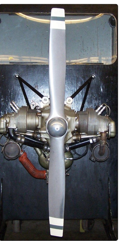
Introduction
A fixed-pitch propeller is one of the most elegantly simple components on a light aircraft: a single rigid assembly whose blade angle—the angle the chord line of each blade makes with the plane of rotation—is set once at manufacture and never changed in flight. Unlike constant-speed or controllable-pitch propellers, a fixed-pitch design has no governor, no pitch-change mechanism, and no oil passages. What it does have is a carefully engineered combination of geometry, materials, and internal structure that must withstand enormous centrifugal loads, bending forces, and vibration while remaining light enough to avoid penalizing the aircraft's useful load.
For the Aviation Mechanic Technician (AMT) Powerplant candidate, understanding how fixed-pitch propellers are built—what they are made of, how those materials are processed, and why each design decision matters—is essential both for the FAA knowledge exam and for safe maintenance practice in the field. This article walks through the two primary construction materials (wood and aluminum alloy), the manufacturing steps that produce a finished propeller, the structural loads the propeller must survive, and the inspection and regulatory framework that governs its service life.
What "Fixed-Pitch" Really Means
Every propeller blade is essentially a rotating wing. The blade angle (sometimes loosely called pitch) is the angular difference between the chord of the blade at a reference station—typically 75 percent of the blade radius—and the plane of rotation. Because this angle is fixed, the propeller is optimized for one specific combination of airspeed and engine RPM. A climb propeller is set to a lower blade angle, which allows the engine to turn at higher RPM and produce more power at lower airspeeds; this sacrifices cruise efficiency for better initial climb performance. A cruise propeller uses a higher blade angle that loads the engine more at altitude and higher airspeed, reducing RPM slightly but converting that torque into greater forward thrust at cruise—at the cost of a somewhat longer takeoff roll and reduced initial climb rate.
Because no single blade angle is perfect for all flight conditions, fixed-pitch propellers are a design compromise. The manufacturer selects the blade angle that best serves the aircraft's intended mission, then optimizes the airfoil section, planform taper, and material selection around that choice.
Wood Propellers: Construction and Materials
Wood was the original propeller material and remains FAA-approved for many light aircraft today. A quality wood propeller is not carved from a single log. Instead, it is a laminated assembly typically composed of five to nine individual planks of carefully selected hardwood, glued together with their grain running in alternating directions to minimize warping and splitting.
Approved Wood Species
The FAA's Aviation Maintenance Handbook — Airframe (FAA-H-8083-31) and older CAA/FAA technical standards recognize several hardwoods as acceptable propeller stock, including yellow birch, sugar maple, black walnut, and Sitka spruce. Each species is evaluated for its combination of strength-to-weight ratio, workability, and resistance to checking (surface cracking). Yellow birch has historically been the most common choice for certificated propellers because of its high density and fine, uniform grain.
Lamination and Curing
Each lamination strip is dried to a specific moisture content—typically around eight to twelve percent—before gluing. Excessive moisture causes the finished propeller to shrink, crack, or warp; too little makes the wood brittle. The laminates are bonded under hydraulic pressure with a waterproof adhesive (historically casein-based, but modern production may use resorcinol or epoxy formulations). After curing, the blank is rough-cut to planform shape on a band saw, then finished by hand or CNC tooling to the precise airfoil contour and blade angle specified on the type certificate data sheet (TCDS).
Protective Coatings and Leading-Edge Protection
Bare wood is vulnerable to moisture absorption, which can change the blade's weight distribution and cause imbalance. After finish-sanding, wood propellers receive multiple coats of spar varnish or an equivalent moisture-resistant finish. More critically, the leading edge of each blade is protected by a thin strip of fabric or fiberglass cloth embedded in varnish, and many designs add a metal (typically brass or stainless steel) sheath along the outer leading edge to resist erosion from rain, dust, and gravel. The tip of the blade may also receive metal tipping. Any damage to these protective surfaces must be evaluated carefully because exposed wood can absorb moisture rapidly and lead to sudden imbalance.
Aluminum Alloy Propellers: Construction and Materials
The vast majority of fixed-pitch propellers manufactured today for certificated light aircraft are forged from aluminum alloy, most commonly an alloy in the 2000 series (such as 2025-T6) that combines high strength with the low density essential in rotating components. The T6 temper designation indicates the alloy has been solution heat-treated and artificially aged to near-peak hardness.
The Forging Process
Manufacturing begins with a heated aluminum billet that is pressed or hammered between precision dies in a series of forging steps. Forging aligns the grain structure of the metal parallel to the blade contour, which maximizes fatigue strength far beyond what casting could achieve. After forging, the blade surfaces are machined and hand-finished to the exact airfoil profile specified by the propeller manufacturer. The hub bore, mounting bolt holes, and propeller shaft taper (if applicable) are precision-machined to match the engine's propeller flange per the TCDS.
Surface Treatment
Bare aluminum corrodes in the presence of moisture and dissimilar metals. To prevent this, aluminum propellers are anodized—an electrochemical process that thickens the natural oxide layer on the surface—then painted with a corrosion-inhibiting primer and finish coat. The leading edge and blade tips, which experience the highest erosion rates from particulate matter in the air, may receive a polyurethane topcoat or a bonded abrasion-resistant strip.
Tracking and Balancing
After all machining and coating are complete, each propeller is checked for track (whether both blade tips sweep the same plane of rotation) and static balance (equal mass distribution about the hub centerline). Imbalance as small as a fraction of an ounce-inch can produce vibration severe enough to damage engine mounts, loosen accessories, and fatigue the crankshaft flange. Static balance is corrected by removing small amounts of material from the heavy blade's tip or hub area, or by adding small balance weights in approved locations. Dynamic balancing—done with the propeller spinning on the engine—is not required by regulation for fixed-pitch propellers but is increasingly performed during maintenance to reduce vibration further.
Why Construction Quality Matters
A propeller blade experiences three major force types simultaneously in flight. Centrifugal force—by far the largest—acts to pull each blade straight outward from the hub; at typical light-aircraft RPM, this can impose a tensile load equivalent to tens of thousands of pounds at the blade root. Thrust bending force tends to bend the blade tips forward in the direction of flight. Torque bending force opposes rotation and tries to twist the blade toward a lower blade angle. Aerodynamic forces also induce vibration at the blade's natural resonant frequencies, and the engine's power pulses add another vibration input. Any flaw in material or construction—a delamination in wood, a forging fold in aluminum, a poorly repaired nick—becomes a stress concentrator that can grow into a fatigue crack and ultimately cause a blade separation, which is catastrophic.
Key Numbers and Regulatory Facts
- Reference station for blade angle measurement: 75 percent of the propeller tip radius (per FAA-H-8083-32 and FAA-H-8083-25, and propeller type certificate data sheets).
- Approved repairs to wood propellers are limited in depth and location; repairs to aluminum propellers are even more restricted—typically only minor leading-edge dressing within limits specified in the manufacturer's overhaul manual or the FAA's propeller repair data.
- 14 CFR Part 35 governs propeller type certification; Part 43 governs maintenance and repair. A certificated airframe-and-powerplant (A&P) mechanic may perform minor repairs; major repairs require either FAA-approved data and the mechanic's logbook sign-off or work by a certificated propeller repair station under Part 145.
- Propeller logbooks must record all maintenance, repairs, and alterations per 14 CFR 91.417 (for Part 91 operators), and time since overhaul must be tracked against the manufacturer's TBO recommendation or an airworthiness directive (AD) limit where applicable.
- Nicks and gouges on aluminum blades that exceed allowable limits (as defined in the manufacturer's maintenance manual) cannot simply be filed smooth and returned to service—the blade must be evaluated for subsurface damage before any repair is attempted.
Common Test Traps
- Confusing blade angle with pitch: Technically, "pitch" describes the theoretical distance a propeller would advance in one revolution with no slippage; "blade angle" is the physical angle of the chord. The FAA exam may use both terms, and the reference station (75% radius) is the key testable detail.
- Wood propeller lamination direction: Some students think the laminates all run the same way for strength. In fact, they alternate grain direction to resist warping—the same principle as plywood construction.
- Climb vs. cruise propeller confusion: A low blade angle (less pitch) = climb propeller = allows higher RPM. A high blade angle (more pitch) = cruise propeller = lower RPM at cruise speed. Students frequently reverse these.
- Who may perform propeller repairs: Many students assume any A&P can perform any propeller repair. In reality, major repairs require approved data; some work requires a Part 145 repair station. Always check whether the repair is classified as minor or major under 14 CFR Part 43, Appendix A.
- Static vs. dynamic balance: The FAA knowledge test focuses on static balance (mass distribution at rest) for fixed-pitch propellers. Dynamic balance—measuring imbalance while the assembly spins—is a concept associated more with constant-speed installations but is an increasingly common maintenance practice even on fixed-pitch aircraft.