A fixed-pitch propeller is a compromise — it works reasonably well across a range of flight conditions, but it is never truly optimized for any single one of them. The controllable-pitch propeller solves this problem by allowing the blade angle to be changed during flight, matching the propeller's bite of air to the power demands of each flight regime. Understanding how these systems work, why they are used, and how a pilot or mechanic should think about them is essential knowledge for anyone pursuing an Aviation Maintenance Technician (AMT) Powerplant certificate.
Controllable-pitch propellers appear in several forms — from simple two-position designs to fully automatic constant-speed units — but they all share the same fundamental principle: changing the blade pitch angle changes the load on the engine, and therefore the engine's RPM and efficiency. Mastery of this concept connects directly to how you will maintain, troubleshoot, and inspect these systems throughout your career.
Propeller Blade Angle Fundamentals
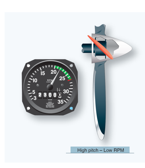
Before diving into controllable-pitch operation, it helps to be precise about terminology. Blade angle (sometimes called pitch angle) is measured between the chord line of the propeller blade and the plane of propeller rotation. A low blade angle (fine pitch) presents a small angle relative to the plane of rotation — the blade takes a shallow bite of air, produces less thrust per revolution, and places a lighter load on the engine, allowing it to spin at higher RPM. A high blade angle (coarse pitch) presents a steeper angle — the blade takes a larger bite, produces more thrust per revolution, and places a heavier load on the engine, reducing RPM.
The concept of geometric pitch describes the theoretical distance a propeller would advance through the air in one revolution if there were no slippage. In practice, the propeller always advances less than its geometric pitch; the difference is called slip. Effective pitch is the actual distance advanced per revolution. Controllable-pitch propellers allow the geometric pitch to be matched to flight conditions, minimizing slip and maximizing efficiency.
How Controllable-Pitch Systems Work
In a simple two-position controllable-pitch propeller, the pilot selects either low pitch (for takeoff and climb) or high pitch (for cruise) using a cockpit control. This is an improvement over a fixed-pitch propeller, but it is still a compromise between two settings rather than a continuously optimized value.
The far more common and practical system is the constant-speed propeller, which uses a governor to automatically maintain a pilot-selected RPM regardless of changing flight conditions. The governor is the heart of the system. It is an engine-driven device that senses propeller shaft speed and uses that information to direct oil pressure to or from the propeller hub, rotating the blades to the exact angle needed to maintain the selected RPM.
The Governor in Detail
Inside the governor, a set of flyweights rotates at a speed proportional to engine RPM. The flyweights are connected to a pilot valve — a small spool valve that controls the flow of oil. When RPM is exactly at the selected value, the flyweights are in on-speed condition and the pilot valve is centered, blocking oil flow. When RPM rises above the selected value (an overspeed condition), the flyweights fly outward, moving the pilot valve to direct high-pressure oil into the propeller hub. This oil pressure acts on a piston that rotates the blades toward high pitch (coarse), increasing the load and slowing the engine back to the selected RPM. When RPM falls below the selected value (an underspeed condition), the flyweights move inward, the pilot valve moves to allow oil to drain from the hub, and a combination of counterweights, aerodynamic twisting moment, and (in many designs) an internal spring rotates the blades toward low pitch (fine), reducing the load and allowing RPM to return to the selected value.
The propeller control in the cockpit adjusts the speeder spring tension in the governor, which sets the RPM at which the flyweights are in balance. Moving the propeller control forward increases the speeder spring tension, requiring the flyweights to spin faster before they overcome the spring — this selects a higher RPM. Moving the control aft decreases spring tension and selects a lower RPM.
Oil Pressure and Blade Movement
Most single-engine aircraft constant-speed propellers use oil pressure to drive the blades toward high pitch and rely on counterweights and aerodynamic forces to drive them toward low pitch when oil pressure is released. This is an important safety consideration: a loss of oil pressure will drive the blades toward low pitch (high RPM), which is a runaway-engine risk but keeps the engine producing power. Some designs — including many multi-engine aircraft propellers — use oil pressure to drive blades toward low pitch and a feathering spring or nitrogen charge to drive them toward high pitch (feather), so that a loss of oil pressure automatically feathers the propeller and reduces drag on a failed engine. Knowing which direction oil pressure moves the blades in a specific installation is critical for troubleshooting and safety analysis.
Feathering Propellers
Feathering is the act of rotating the propeller blades to a blade angle of approximately 90 degrees to the plane of rotation — essentially edge-on to the airflow. A feathered propeller produces almost no drag and stops windmilling, which is critical when an engine fails on a multi-engine aircraft. Without feathering, a windmilling propeller on a failed engine creates enormous drag, severely degrading climb performance and controllability. Feathering systems typically use a separate accumulator charged with engine oil or nitrogen to provide the hydraulic force needed to drive the blades to the feather position even after engine shutdown.
Why It Matters — Efficiency and Safety
The practical advantage of a controllable-pitch propeller is the ability to match engine power output to propeller load across all flight regimes. During takeoff, the pilot selects low pitch and high RPM so the engine can develop its rated horsepower — high RPM means maximum power strokes per minute and maximum thrust. During cruise, the pilot reduces RPM by selecting a higher blade angle. The engine turns more slowly, the power strokes are fewer but more efficient, fuel burn decreases, and engine wear is reduced. This is analogous to shifting into a higher gear in an automobile.
From a maintenance perspective, constant-speed propeller systems require careful attention to governor adjustment, oil tightness at the hub and blade seals, and blade track and balance. An out-of-adjustment governor can cause hunting (RPM oscillating above and below the set value), failure to reach maximum RPM on takeoff, or an inability to feather. These are airworthiness concerns that an AMT must be able to diagnose and correct.
Key Numbers and Rules
- Low pitch / fine pitch: small blade angle, low load on engine, allows maximum RPM — used for takeoff and climb.
- High pitch / coarse pitch: large blade angle, heavy load on engine, reduces RPM — used for cruise and fuel economy.
- Feather: approximately 90° blade angle to the plane of rotation — stops windmilling, minimizes drag on a failed engine.
- On-speed: governor flyweights balanced, pilot valve centered, no oil flow — propeller maintains selected RPM.
- Overspeed: flyweights fly out, governor directs oil to increase pitch (in most single-engine designs) and reduce RPM.
- Underspeed: flyweights move in, oil drains from hub, pitch decreases (fine), RPM increases back to set value.
- Oil pressure failure: most single-engine designs go to low pitch (high RPM); most multi-engine feathering designs go to feather.
- Per 14 CFR Part 23 and 25 type design requirements, controllable-pitch propellers must meet specific feathering time and structural load standards.
Common Test Traps
- Confusing pitch and RPM direction: A common mistake is thinking high pitch means high RPM. The opposite is true — high pitch places more load on the engine, which reduces RPM. Low pitch allows the engine to spin freely at high RPM.
- Governor oil pressure direction: Test questions often assume students don't know which direction oil pressure moves the blades. In most single-engine constant-speed propellers, oil pressure drives blades toward high pitch (coarse). In most multi-engine feathering systems, oil pressure drives blades toward low pitch, and loss of pressure feathers the prop. Always know your specific design.
- Speeder spring misidentified: Students sometimes confuse the speeder spring (which sets the target RPM) with the flyweights (which sense actual RPM). The pilot adjusts the speeder spring tension via the propeller control — the flyweights respond to what the engine is actually doing.
- Feather angle misquoted: Feather is approximately 90 degrees to the plane of rotation — not 90 degrees to the relative wind or chord line. Confusing this reference plane is a common error.
- Two-position vs. constant-speed: A two-position propeller is controllable but NOT constant-speed. A constant-speed propeller uses a governor to automatically maintain RPM; a two-position propeller only offers two fixed blade angle choices and requires the pilot to select between them manually.