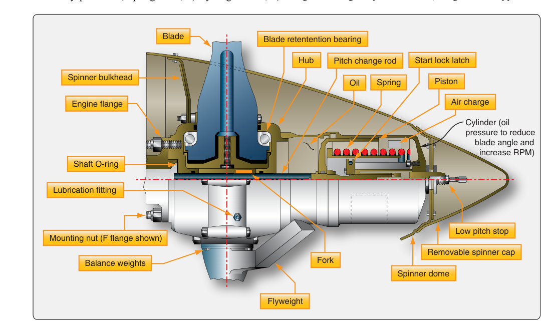
When an engine fails on a multi-engine aircraft, the propeller attached to that engine does not simply stop — it continues to spin in the airstream, a phenomenon called windmilling. A windmilling propeller creates enormous aerodynamic drag, far exceeding the drag of a stopped propeller, and can make an otherwise manageable emergency into a catastrophic loss of control. The solution built into virtually every multi-engine and turboprop powerplant installation is the feathering system, which rotates the propeller blades to a very high pitch angle — typically between 85° and 90° — so that the blade's chord line is aligned nearly edge-on with the relative wind, minimizing drag and, critically, rotational force. This stops the propeller and reduces drag to a minimum, giving the remaining engine or engines the best possible chance to sustain flight.
Understanding propeller feathering — the mechanical principles behind it, how oil-pressure and spring-counterweight systems work, the procedures for accomplishing it in flight, and the maintenance tasks that keep these systems reliable — is essential knowledge for any Aviation Maintenance Technician working on propeller-equipped aircraft.
Why Windmilling Is So Dangerous
A typical constant-speed propeller in the flat-pitch, low-angle position presents a large, disc-like frontal area to the airstream. When the engine stops producing power but the aircraft is still moving forward, ram air strikes those nearly-flat blades and forces them to rotate — windmilling. The aerodynamic drag of a windmilling propeller on a light twin can be two to four times greater than the parasite drag of the entire engine nacelle with a stopped, feathered propeller. On larger turboprop and piston transports the penalty is even more severe. That drag asymmetry degrades climb performance, increases fuel burn on remaining engines, and — on aircraft with critical engine considerations — can threaten control authority. Feathering eliminates nearly all of that drag at the cost of a simple hydraulic or mechanical action.
How Feathering Systems Work
Oil-Pressure Feathering (Counterweight and Spring-Assisted)
Most light and medium twin-engine piston aircraft use a governor-controlled, oil-pressure system to control propeller pitch. In normal constant-speed operation, engine oil pressure, regulated by the governor, acts on a piston or servo inside the propeller hub to move the blades toward low pitch (high RPM). A counterweight assembly on each blade shank, combined with blade-twisting aerodynamic moments, tends to drive the blades toward high pitch — and in feathering systems, these forces are specifically calibrated so that if oil pressure is lost, the counterweights and internal springs push the blades all the way to the feather position, rather than to flat pitch.
This is a critical design philosophy: feathering propellers fail safe toward feather. If the engine seizes and oil pressure drops to zero, the propeller will automatically feather without pilot action, provided the aircraft speed is above the minimum windmilling speed required to sustain blade rotation against the counterweight force. On most systems the pilot can also command feathering manually by pulling the propeller control lever aft of the low-RPM detent into a marked feather gate or position. This repositions the governor speeder spring and directs oil out of the hub, allowing springs and counterweights to drive the blades to feather angle.
Accumulator-Assisted Feathering
Because feathering requires moving oil out of the propeller hub quickly — and a stopped or seizing engine may provide little pump pressure — many aircraft installations include a feathering accumulator. This small pressurized reservoir stores oil under nitrogen pre-charge pressure (or hydraulic system pressure on larger aircraft) so that a charge of high-pressure oil is available to assist rapid blade movement to feather even after engine oil pressure has collapsed. The accumulator is charged automatically during normal engine operation and is checked for proper pre-charge pressure as part of routine maintenance inspections.
Electric Feathering Pumps
Some aircraft, particularly larger piston twins and some turboprops, supplement or replace the accumulator with a dedicated electric feathering pump — an electrically driven oil pump that supplies pressure on demand when the pilot selects feather. The pump draws from the engine oil system and directs flow through a feathering valve. These systems allow positive, pilot-commanded feathering independent of engine oil pressure and are common on aircraft where rapid, positive feather action is critical to certification performance guarantees.
Turboprop Feathering
Turboprop propeller systems follow similar hydraulic principles but are often integrated with the engine's propeller control unit (PCU) or full-authority digital engine control (FADEC). Many turboprop installations incorporate a negative torque sensing (NTS) system that automatically commands feathering if the engine begins absorbing power from the propeller (a condition indicating flame-out or mechanical failure) before the pilot can respond. Autofeather systems, armed during takeoff, are designed to command feathering very quickly — typically within a fraction of a second to a couple of seconds of detecting a torque drop below a set threshold — with exact response times specified by the aircraft manufacturer, protecting performance during the most critical phase of flight.
Mechanical Components of a Feathering Propeller Hub
A typical feathering constant-speed propeller hub contains the following major components that an AMT must be familiar with:
- Blade pitch-change mechanism: A hydraulic piston or cam-and-gear assembly that translates oil pressure into blade rotation about the blade's spanwise axis.
- Governor oil transfer valve: Directs high-pressure oil into or out of the pitch-change cylinder based on governor commands.
- Counterweights: Cast or machined masses attached to blade shanks offset from the pitch-change axis, generating centrifugal twisting moment toward high (feather) pitch.
- Feathering spring: A compression spring in the hub that assists counterweights in driving blades toward feather, particularly at low RPM when centrifugal counterweight force is insufficient.
- Feather stop pins or latches: Mechanical stops that define the exact feather blade angle (commonly 85°–90° on piston aircraft, verified at installation and during overhaul).
- Unfeathering accumulator port: A fitting that connects the hub to the accumulator for rapid pitch-change capability during engine restart sequences.
Unfeathering: Restarting and Returning Blades to Flat Pitch
Feathering is not always permanent in a flight situation. Pilots may feather a propeller due to an engine roughness event, investigate, and then attempt an in-flight restart. To restart, the engine must be motored — brought to rotation — before ignition can occur. Unfeathering procedures vary significantly by aircraft type: some systems use the unfeathering accumulator to supply a burst of oil pressure that drives the blades back toward low pitch enough for the airstream to windmill the propeller and rotate the engine, while other installations rely on the starter motor to bring the engine and propeller to rotation as part of the unfeathering sequence. The specific method, and the sequence of governor, control lever, and starter actions, must be followed exactly as published in the aircraft's AFM/POH for that make and model. The AMT must ensure the accumulator is properly charged to a specified nitrogen or hydraulic pre-charge pressure (typically listed in the aircraft maintenance manual) to guarantee adequate oil volume for the unfeathering cycle.
Maintenance Inspection and Airworthiness Considerations
Feathering system maintenance is governed by the propeller and airframe manufacturer's maintenance manuals, with overarching regulatory requirements in 14 CFR Part 65 (for the certificated mechanic performing the work) and 14 CFR Part 43 (maintenance standards). Key AMT tasks include:
- Operational check: Verify propeller feathers and unfeathers smoothly through the full angular range during ground run-up, observing RPM drop as blades move toward feather and confirming blade movement stops cleanly at the feather detent.
- Accumulator pre-charge check: Verify nitrogen or air pre-charge pressure with engine shutdown per the maintenance manual; low pre-charge allows oil to bypass the bladder and reduces unfeathering effectiveness.
- Governor and feathering valve inspection: Inspect for oil leaks, verify proper governor speeder spring setting, and confirm the feather detent or gate in the cockpit control operates the governor stop correctly.
- Blade angle verification: Use a blade angle protractor at the reference station called out in the propeller specification (commonly 30 inches from the hub centerline on light aircraft) to confirm feather angle matches the type certificate data sheet (TCDS) value.
- Counterweight and spring condition: Inspect counterweight bolts for proper torque and safety, and check feathering springs for set, corrosion, or fatigue cracks at overhaul intervals.
- Feathering latch/stop wear: Inspect stop surfaces for fretting or impact damage that could alter the rigged feather angle.
Key Numbers and Rules
- Typical feather blade angle: 85° to 90° measured from the plane of rotation at the manufacturer's reference blade station.
- Counterweight centrifugal force toward feather is proportional to RPM squared — at very low RPM, the feathering spring must provide the twisting moment.
- Accumulator pre-charge pressure: specific to each aircraft model; always verify against the maintenance manual, not generic values.
- Blade angle verification reference station: specified in the TCDS and propeller specifications — never assumed.
- Autofeather systems (turboprops) are typically armed at or above a specified torque setting before takeoff and disarmed after clearing a safe altitude — check AFM for each specific aircraft.
- Maintenance on feathering systems that involves disassembly of the propeller hub or pitch-change mechanism generally requires propeller overhaul capability, which may be held by an appropriately rated certificated mechanic or repair station under 14 CFR Parts 43 and 65, or by a certificated repair station under 14 CFR Part 145 — the specific rating and facility required depends on the scope of work and the propeller manufacturer's instructions.
Common Test Traps
- Confusing pitch direction: High pitch = coarse = feather (large angle, slow RPM). Low pitch = fine = flat (small angle, high RPM). Students sometimes reverse these on written exams.
- Assuming oil pressure feathers the prop: In most feathering designs, oil pressure holds the blades in LOW pitch. Loss of oil pressure allows springs and counterweights to drive to HIGH pitch (feather). The direction of oil-pressure action varies by design, so always verify by aircraft model.
- Forgetting the feathering spring's role at low RPM: Counterweights depend on centrifugal force and are ineffective at very low RPM; the spring is what drives the blades to feather during the final stages of engine slowdown.
- Neglecting accumulator pre-charge: An accumulator with depleted pre-charge may feel normal on a static inspection but fail to unfeather the propeller in flight — making pre-charge verification a critical maintenance step, not a formality.
- Blade angle measurement station errors: Measuring at the wrong spanwise station produces incorrect angle readings. The reference station is model-specific and must be taken from the TCDS or propeller overhaul manual, not estimated.