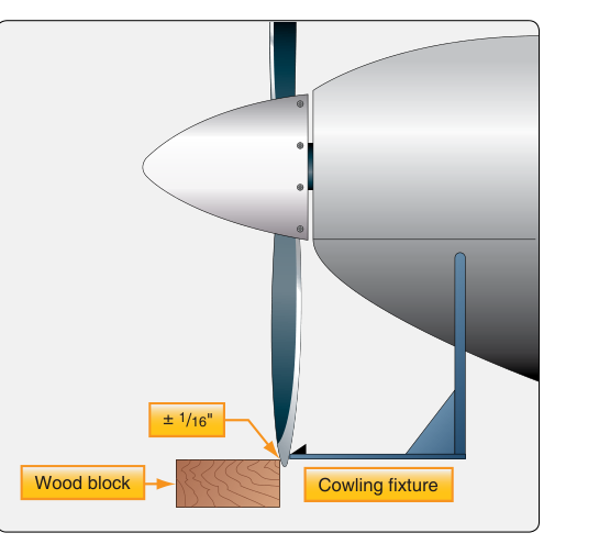
When a propeller spins at cruise power, each blade traces a circular arc called its track. For a healthy, properly installed propeller, every blade should pass through exactly the same plane — ideally within a very small tolerance of each other. When one or more blades deviate from that common plane, the propeller is said to be out of track. Out-of-track conditions create asymmetric thrust and aerodynamic imbalance, producing vibration that can damage engine mounts, airframe structure, and the propeller itself. Learning to perform a thorough track inspection — and understanding when adjustment is warranted versus when the propeller or hub must come off — is an essential skill for any Aviation Maintenance Technician (AMT) working on powerplants.
This article covers the theory behind propeller track, the step-by-step inspection procedure, acceptable tolerances, common causes of out-of-track conditions, approved adjustment methods, and the regulatory framework that governs propeller maintenance. The information is grounded in the Aviation Maintenance Handbook — Powerplant (FAA-H-8083-32) and applicable 14 CFR provisions.
What Propeller Track Is and Why It Matters
The track of a propeller is the path each blade tip traces as the propeller rotates one full revolution. Ideally every blade tip should pass through identical points in space, describing a single flat disc perpendicular to the crankshaft centerline. Deviation from that ideal — where one blade tip passes through a plane slightly forward or aft of another blade tip's plane — is the out-of-track measurement, expressed in inches or fractions of an inch.
Even a small out-of-track condition introduces an aerodynamic asymmetry: one blade generates slightly more or less thrust than its neighbors on each revolution, creating a periodic force at propeller rotational frequency. This cyclic loading is transmitted directly through the crankshaft and engine mounts. At typical cruise RPM, even a 1/8-inch discrepancy can produce a noticeable vibration signature that, over time, fatigues engine mount bolts, loosens cowling fasteners, and accelerates wear on engine accessories. Severe out-of-track conditions can indicate a bent blade, an improperly torqued hub, or a damaged crankshaft flange — each of which is a potentially catastrophic failure mode.
How a Track Inspection Is Performed
Before beginning any propeller inspection, confirm the aircraft is secured, the ignition is off and verified with a placard or key removed, and all applicable safety precautions are in place. Never treat a propeller as safe to move by hand without confirming the magnetos are grounded.
Setting Up the Reference Point
The classic track inspection method uses a fixed reference point near the blade tip path. Position a sturdy stand, block of wood, or commercially available track-checking tool so that a pointer or chalk mark just barely clears one blade tip at its lowest point of rotation. The reference must be absolutely stationary — any movement in the stand invalidates the measurement. Some AMTs chalk the ground below the blade arc and use a plumb bob; others use a dedicated track gauge clamped to the engine cowling or a ground-level fixture.
Rotating Each Blade to the Reference
With one blade positioned at the reference point — usually the six-o'clock (straight down) position for horizontal-shaft engines — note the exact gap or contact point between the blade tip and the reference marker. Mark that position. Then carefully rotate the propeller so the next blade reaches the same six-o'clock position and observe whether its tip passes through the same point, is forward of it, or is aft of it. Record the deviation for each blade. On a two-blade propeller you compare two measurements; on a three-blade, three; and so on.
Measuring the Deviation
Use a feeler gauge, ruler, or the calibrated scale on a track gauge to quantify the difference between the highest and lowest blade tip positions. The total out-of-track measurement is the maximum difference found between any two blades. For most fixed-pitch wood or aluminum propellers, the FAA-H-8083-32 and applicable manufacturer data generally consider track deviations of 1/16 inch (approximately 1.6 mm) or less acceptable, though always defer to the specific manufacturer's service manual because tolerances vary by propeller model and diameter. Constant-speed and controllable-pitch propellers have their own manufacturer-specified limits.
Common Causes of Out-of-Track Conditions
Understanding why a propeller goes out of track is as important as measuring the deviation. The most frequent causes include:
- Blade damage: Ground strikes, FOD (foreign object debris) impacts, or leading-edge nicks can permanently deform a blade, bending it out of its original plane. Even a minor tip strike can alter blade geometry without obvious visible damage.
- Improper installation: On fixed-pitch propellers bolted to a flange, a blade hub not seated fully, unevenly torqued bolts, or missing washers can tilt the propeller disc relative to the crankshaft flange.
- Hub or flange damage: A bent crankshaft flange or a hub with worn or deformed bolt holes will force the propeller disc out of plane regardless of how carefully the propeller itself is installed.
- Wood propeller warping: Wood absorbs and releases moisture. A wooden propeller stored improperly or operated in extreme humidity changes can warp slightly, causing individual blades to shift out of the common track plane.
- Internal hub defects (constant-speed propellers): On constant-speed designs, internal components such as pitch-change mechanisms, counterweights, or beta pins can shift or wear, altering the geometric relationship between blades.
Approved Adjustment Methods
The corrective action depends entirely on the cause and the propeller type. AMTs must never attempt to bend a metal blade back into track — bending introduces stress concentrations and internal cracks that are invisible to the naked eye and can lead to fatigue failure in flight. Similarly, carving or sanding a wood propeller to correct track is not an approved technique and will alter its balance and aerodynamic characteristics.
For fixed-pitch metal or wood propellers bolted to a flange, the first corrective step is to remove the propeller, clean the mating surfaces, and re-inspect the crankshaft flange for runout using a dial indicator. If the flange is within serviceable limits, reinstall the propeller carefully, seating it fully, inserting all hardware correctly, and torquing the mounting bolts in a star (alternating) pattern to the manufacturer's specified torque values. Recheck track after reinstallation. If track is still out of tolerance, the propeller should be sent to an FAA-certificated propeller repair station for further inspection and disposition.
For constant-speed propellers, an out-of-track finding almost always means the hub assembly must be removed and inspected by a certificated propeller repair station. These propellers have complex internal mechanisms, and blade angle adjustments in the field are tightly controlled by manufacturer procedures and 14 CFR Part 65/Part 145 authority requirements.
Shims or spacers are sometimes used between the propeller hub and the engine flange to correct minor flange runout, but only when specifically authorized by the engine and propeller manufacturer's data. Any such modification must be documented in the aircraft maintenance records.
Regulatory Framework
Propeller maintenance falls under 14 CFR Part 65 (certification of AMTs), 14 CFR Part 43 (maintenance, preventive maintenance, rebuilding, and alteration), and the specific propeller type certificate data sheet (TCDS). Under 14 CFR Part 43, Appendix A, a track inspection and minor adjustment (such as re-torquing mounting bolts) typically falls within the scope of work an Airframe and Powerplant (A&P) certificated mechanic may perform. However, any repair that involves straightening blades, welding, or altering the propeller's certified geometry requires a certificated propeller repair station operating under 14 CFR Part 145.
All propeller maintenance — inspections, adjustments, repairs — must be documented in the aircraft maintenance records per 14 CFR §43.9, including the date, description of the work, regulatory basis, and the signature and certificate number of the responsible mechanic.
Key Numbers and Rules
- Typical track tolerance: 1/16 inch or less for most fixed-pitch propellers — always verify with the manufacturer's service manual.
- Reference method: Fixed-point comparison at the blade tip, with the propeller rotated so each blade passes the same reference position.
- Never straighten bent metal blades in the field — send to a certificated repair station.
- Re-torque in a star pattern to the manufacturer's specified values when reinstalling to correct installation-related track errors.
- Crankshaft flange runout must be measured with a dial indicator and compared to engine manufacturer limits before assuming the propeller itself is at fault.
- Document everything per 14 CFR §43.9 regardless of how minor the adjustment appears.
Common Test Traps
- Confusing track with balance: Track describes whether blades sweep the same plane; balance describes whether mass is equally distributed around the hub. A propeller can be in perfect track but dynamically unbalanced, or vice versa. These are separate inspections with different tools and criteria.
- Assuming any deviation means a new propeller: Minor deviations due to improper installation can often be corrected by careful removal and reinstallation with proper torque — but only after verifying the cause. Do not assume the propeller itself is defective without checking the flange first.
- Forgetting to check crankshaft flange runout: Many test questions present out-of-track scenarios where the propeller is fine but the crankshaft flange is bent. Always check flange runout as part of the diagnostic process.
- Bending blades as an acceptable repair: FAA knowledge test questions sometimes offer blade straightening as a field repair option. This is never acceptable for certificated propellers — it is not an approved technique.
- Ignoring documentation requirements: Even a simple re-torque of propeller bolts must be logged. Failure to record maintenance is a regulatory violation under 14 CFR Part 43 and a common distractor on written exams.