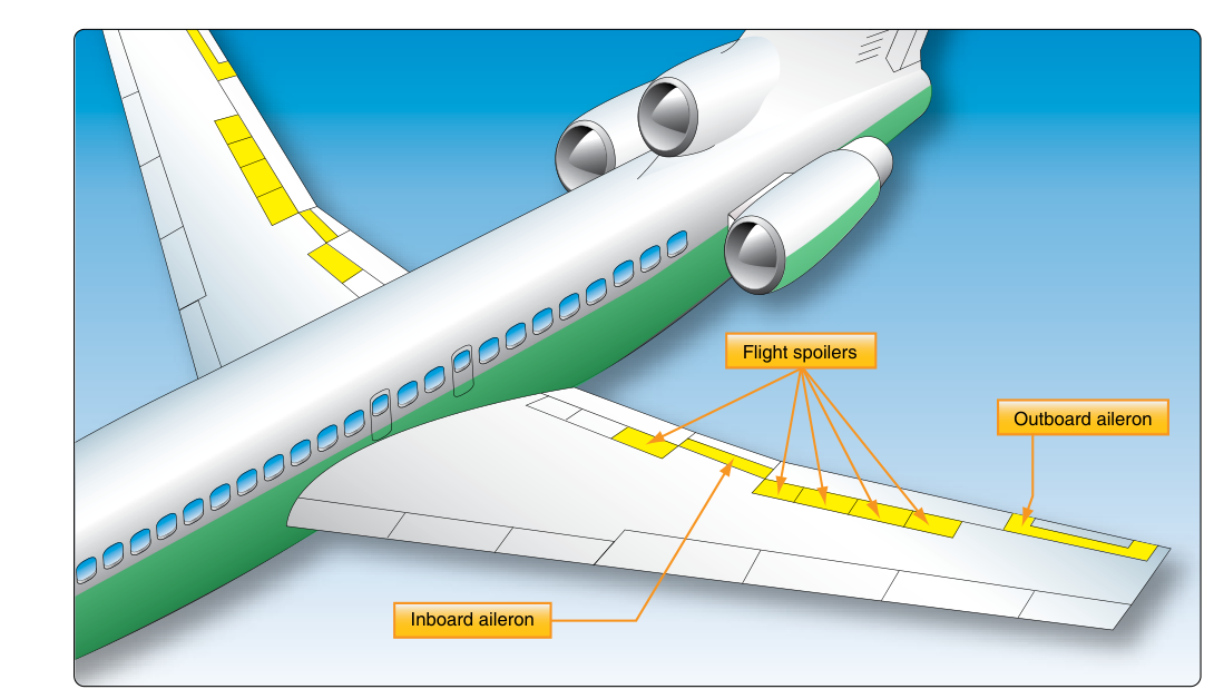
In a conventional light aircraft, the pilot's control inputs travel through cables, pushrods, and bellcranks to directly reposition the ailerons, elevator, and rudder. The relationship is mechanical and immediate. In a modern transport-category jet, that tactile chain is largely replaced by fly-by-wire (FBW) technology: pilot inputs are converted to electrical signals, routed to flight control computers, processed, and then transmitted to electrohydraulic or electromechanical actuators that physically move the control surfaces. The computers are not passive relays—they actively interpret, filter, shape, and sometimes override what the pilot commands before anything happens at the wing or empennage. For the ATP candidate, understanding FBW at a systems level is essential not only for written test preparation but for the kind of crew resource management and abnormal-procedure knowledge demanded of transport-category pilots.
How Fly-By-Wire Works
At its core, a FBW system replaces the direct mechanical linkage between the cockpit and control surfaces with an electronic signal pathway. When the pilot moves a sidestick, conventional column, or rudder pedals, position transducers convert the mechanical displacement into electrical signals. These signals are sent to flight control computers (FCCs), which compute the appropriate surface deflection commands based on the pilot's intent, the aircraft's current flight envelope state, and pre-programmed control laws. The computed commands are then sent to hydraulic servo actuators or, in some designs, electromechanical actuators (EMAs), which physically move the surfaces.
Redundancy architecture
Because a single computer failure could theoretically deprive the crew of all control authority, every certified FBW system is designed around rigorous redundancy. Typical designs use multiple independent computer channels—often three or more—that cross-monitor each other and vote on the correct output. If one channel produces an anomalous result, the majority vote excludes it. Many designs go further and employ dissimilar redundancy: the backup computers run software written by a different team, in a different programming language, on different hardware. This guards against a common-mode software bug or hardware defect causing simultaneous failure of all channels. Hydraulic power is similarly redundant, with independent hydraulic circuits cross-feeding critical actuators so that losing a single engine-driven pump does not leave a surface without motive power. Some aircraft also incorporate electrical backup actuators or mechanical reversion for specific surfaces as a final layer of protection.
Control laws and degraded modes
The term control law describes the relationship between the pilot's input and the resulting surface command at any given moment. Note that "normal law," "alternate law," and "direct law" are Airbus-specific terminology for describing this relationship; other manufacturers use different architectures and naming conventions to achieve similar goals (for example, Boeing's 777/787 FBW systems use a pitch-rate/attitude command structure without this same three-tier nomenclature). Under normal law, the computers provide the full suite of envelope protections and may transform the pilot's column or stick displacement into a commanded flight parameter—pitch rate, load factor, or bank angle—rather than a simple surface deflection. On Airbus aircraft this is described as a load-factor demand system, while Boeing's 777/787 FBW architecture uses a distinct pitch-rate/attitude command philosophy; the two approaches share the goal of translating pilot intent into a flight-path command while enforcing structural and aerodynamic limits, but they are implemented differently and are not interchangeable terms.
If sensor failures or computer faults reduce available computing resources, the system degrades to alternate law, in which some protections are removed or simplified. Further degradation produces direct law, where the pilot's stick or column displacement produces a proportional surface deflection with little or no envelope protection—analogous to operating a conventional aircraft. Some designs include a final mechanical backup for critical surfaces such as the horizontal stabilizer or rudder, ensuring some degree of pitch and directional control even with complete electrical failure. Each degraded mode carries specific handling characteristics, limitations, and crew procedures that ATP candidates must know.
Envelope Protection: The Safety Net
The most operationally significant feature of FBW in transport aircraft is envelope protection. The flight control computers continuously monitor the aircraft's state—angle of attack, airspeed, Mach number, load factor, bank angle, and pitch attitude—against the certified structural and aerodynamic limits. When a pilot command would push the aircraft toward or beyond a limit, the system intervenes.
- Angle-of-attack (alpha) protection: As the aircraft approaches the critical angle of attack, the system limits further aft stick commands, may apply automatic nose-down pitch input, and provides strong tactile or pitch feedback. This can prevent an aerodynamic stall even if the pilot holds continuous back pressure.
- Load factor protection: The computers cap positive and negative g-loading to the aircraft's certified structural limits, protecting against overstress during aggressive turbulence recovery or escape maneuvers.
- High-speed protection: Approaching VMO/MMO, the system may apply automatic nose-up input or restrict further nose-down commands, guarding against a high-speed upset or structural exceedance.
- Bank angle protection: Beyond a design-defined bank angle, the system resists further roll input. When the pilot releases the stick, the aircraft tends to return toward a wings-level attitude. On Airbus normal law, this threshold is commonly cited as approximately 67°, but this figure is specific to Airbus's FBW design philosophy and is not a generic transport-category FBW standard—know your aircraft's specific approved flight manual limits.
- Pitch attitude protection: Extreme nose-high or nose-low pitch attitudes may trigger automatic corrective inputs or restrict commands that would worsen the upset.
It is critical to understand that envelope protections operate only in normal law. In alternate law many protections are reduced, and in direct law they are essentially absent. The crew cannot rely on the aircraft to prevent a stall or structural overstress in degraded modes—full pilot responsibility for staying within limits is restored.
Operational Implications for Transport-Category Crews
Sidestick priority and dual-input hazards
On aircraft equipped with dual sidesticks—one for each pilot—inputs from both sticks are typically summed algebraically or managed through a priority logic system. On some designs, simultaneous opposing inputs can partially cancel each other, producing an unexpected flight path that neither pilot intended. This characteristic has been implicated in serious accidents. Crew coordination procedures require clear communication when one pilot intends to take over control, and most designs include a priority pushbutton that transfers authority to one pilot while locking out the other, accompanied by an aural and visual annunciation.
FBW versus autopilot
A frequent point of confusion is the relationship between FBW and the autopilot. They are distinct systems. The FBW flight control computers process manual pilot inputs during hand-flying. The autopilot is a separate system that generates its own surface commands—which happen to travel through the same FBW actuator paths. Both systems can coexist, but they serve fundamentally different purposes. Disengaging the autopilot returns control to the pilot through the FBW system; it does not change the control law or reduce envelope protection.
Trim, load alleviation, and fuel efficiency
FBW enables capabilities that go beyond safety protection. The computers can continuously and automatically reconfigure control surface scheduling to compensate for configuration changes, shift control authority between redundant surfaces when one is degraded, and optimize surface positions to minimize drag—improving fuel efficiency over long sectors. Wing load alleviation systems can deflect ailerons and spoilers to redistribute bending loads during turbulence, reducing structural fatigue. These functions occur transparently to the crew but represent a fundamental departure from the way older aircraft manage control authority.
Key Numbers and Rules
- FBW systems use dissimilar hardware and software on independent channels to prevent common-mode faults from defeating all redundancy simultaneously.
- Normal law typically provides the full protection envelope; alternate law and direct law progressively remove protections as system health degrades. (Note: this three-tier "law" terminology is Airbus-specific; other manufacturers use different architectures and naming.)
- Bank angle protection thresholds vary by manufacturer—Airbus normal law is commonly referenced at approximately 67°—know your aircraft's specific approved flight manual limits.
- Mechanical backup for critical surfaces (horizontal stabilizer, rudder) may exist as a final reversion mode; crew procedures for activating or recognizing this mode are AFM-specific.
- In direct law, the aircraft is essentially a conventional airplane: the pilot is solely responsible for staying within Vmo/Mmo, load factor limits, and stall margins.
Common Test Traps
- FBW is not an autopilot. The flight control computers process manual inputs; the autopilot is a separate, layered system that shares the same actuator paths but has a distinct function and failure mode.
- Degraded law means degraded protection. Candidates sometimes assume that redundancy means protections are always available. After multiple failures, the aircraft can enter direct law with no stall, overspeed, or load-factor protection whatsoever.
- Dual sidestick inputs are not always additive. On some designs inputs are summed, on others a priority logic applies. Assuming one design's behavior applies to all aircraft is a test trap and an operational hazard.
- Redundancy is not invulnerability. Cascading failures—dual hydraulic loss, multiple air data sensor failures—can strip the system down to degraded modes faster than crews sometimes expect. Knowing the entry conditions and crew actions for each mode is an ATP systems knowledge requirement.
- Envelope protection does not replace stick-and-rudder skill. The ACS still requires ATP applicants to demonstrate precise manual flight and upset recovery. Protection systems are a safety net, not a substitute for proficiency.