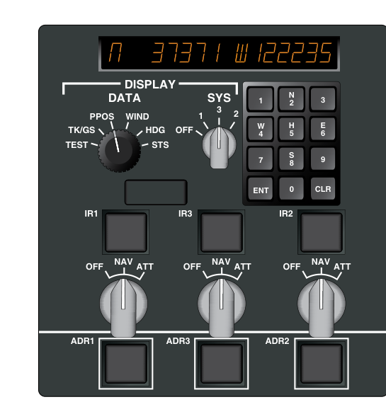
Modern transport-category aircraft depend on an Air Data and Inertial Reference System (ADIRS) as the nerve center of virtually every flight-critical computer, display, and autoflight function on board. Rather than employing separate, stand-alone boxes for air data computation and inertial navigation, the ADIRS architecture consolidates both functions into a single line-replaceable unit called an Air Data/Inertial Reference Unit (ADIRU). Most large transport aircraft — from the Boeing 737NG and 777 families to the Airbus A320 and A330/A340 series — carry three ADIRUs, arranged so that the loss of any one unit does not deprive the flight crew of flight-critical data. Understanding how the ADIRS works, how it aligns, how it degrades, and how crews manage its failures is fundamental knowledge for the ATP Airman Certification Standards and for safe transport operations in the real world.
Architecture: Two Specialists in One Box
Each ADIRU contains two functionally distinct internal sections that share a common housing but process entirely different physical inputs.
Air Data Reference (ADR) Section
The ADR section is, at its core, a sophisticated air data computer. It accepts pneumatic inputs from the aircraft's pitot probes and static ports and converts those pressure signals into the suite of parameters every downstream system needs. Computed outputs include indicated airspeed (IAS), calibrated airspeed (CAS), true airspeed (TAS), Mach number, pressure altitude, density altitude, vertical speed (barometric), angle of attack (AOA), and total air temperature (TAT). These outputs feed the Primary Flight Displays (PFDs), Flight Management Computers (FMCs), autothrottle and autoflight systems, Traffic Collision Avoidance System (TCAS), Ground Proximity Warning System (GPWS/TAWS), and engine control systems. Because the ADR section depends entirely on pitot and static pressure, any blockage, icing, or contamination of those probes directly degrades ADR outputs while leaving the Inertial Reference section unaffected.
Inertial Reference (IR) Section
The IR section contains an Inertial Measurement Unit (IMU) consisting of a cluster of ring laser gyroscopes (RLGs) and solid-state accelerometers mounted on a strapdown platform — meaning the sensors are fixed to the airframe rather than mounted on a mechanically gimbaled platform as in older systems. Ring laser gyros use the Sagnac effect: two laser beams travel in opposite directions around a closed triangular cavity, and any rotation of the cavity creates a measurable frequency difference between the beams proportional to the angular rate. Because they have no moving parts, RLGs are generally more reliable than mechanical spinning gyros, though at very low rotation rates they can suffer from a phenomenon called lock-in, which designers overcome by dithering the cavity; this makes their response fast but not literally instantaneous or free of engineering compromises.
The accelerometers measure linear accelerations along all three body axes. Onboard computers continuously integrate acceleration to derive velocity, and integrate velocity to derive position — a mathematical process called dead reckoning from known initial conditions. The IR section therefore outputs pitch attitude, roll attitude, magnetic and true heading, body angular rates, ground speed, track angle, wind vector, and present position in latitude and longitude. Critically, none of these outputs require any external radio signal. The IR section delivers valid attitude and navigation data whether GPS, VOR, DME, or any other radio navigation aid is available or not.
Alignment: The Non-Negotiable Pre-Flight Requirement
Before the IR section can provide useful data, it must complete an alignment (initialization) sequence while the aircraft is stationary on the ground. During alignment, the accelerometers sense the local gravity vector to establish a precise vertical reference, and both the gyros and accelerometers work together to sense the very small but measurable rotation of the Earth and solve for true north. This process — called gyrocompassing — is what allows the IR section to establish its initial heading reference without any external magnetic or radio input. Typical alignment time for modern RLG-based systems commonly runs from about 10 to 17 minutes, varying with latitude and the specific system, though the exact duration is manufacturer- and model-specific.
The alignment process is fatally sensitive to aircraft motion. Any movement of the aircraft — even slow taxi — during the alignment sequence will corrupt the inertial data and require a full restart of the alignment. Most systems display alignment status on the ADIRS control panel or a dedicated page on the multifunction display, and they will flag an incomplete or corrupted alignment before allowing IR data to feed flight displays.
Many modern systems offer a stored heading (fast alignment) option when the aircraft has not moved significantly since the last shutdown. In this mode the system retrieves the last known heading from non-volatile memory and uses it as the initial heading reference, reducing alignment time substantially. However, if the aircraft has been repositioned on the ramp, towed, or if significant time has elapsed, a full alignment is required to ensure accuracy.
Inertial Drift and GPS Integration
No inertial system is perfect. Because every integration step compounds tiny measurement errors from the gyros and accelerometers, the IR-derived position gradually diverges from the aircraft's true position over time — a phenomenon called inertial drift. Modern ring laser gyro systems are extraordinarily accurate by historical standards, but on a long oceanic flight lasting eight or more hours, uncorrected IR drift can still accumulate to several nautical miles.
In practice, the FMC continuously blends IR position data with GPS position updates to correct accumulated drift in real time. The blended output — sometimes labeled IRS/GPS or ADIRU/GPS mix — provides position accuracy far superior to unaided inertial navigation, routinely meeting the stringent Required Navigation Performance (RNP) values demanded for oceanic and remote-area operations under FAA and ICAO standards. The GPS receiver does not replace the IR section; it corrects it. Attitude data — pitch, roll, and heading — always comes from the IR gyros and accelerometers, not from GPS.
Display Source Selection and Failure Management
The ADIRS control panel (sometimes called the IR mode selector panel) allows the flight crew to independently power each ADIRU and select the operating mode: OFF, ALIGN, NAV, or ATT (attitude-only mode). In normal operations all three ADIRUs operate in NAV mode throughout the flight.
Each side's PFD and Navigation Display draws air data and inertial data from a designated ADIRU. On many Boeing and Airbus types this is commonly ADIRU 1 for the captain's side and ADIRU 2 for the first officer's side, with ADIRU 3 serving as the standby/center system, but this exact assignment is airplane-specific and crews must consult the applicable aircraft documentation rather than treat it as a universal rule. A switching panel allows the crew to select an alternate ADIRU as the data source for either side when the primary unit fails or produces unreliable data. Recognizing which ADIRU is driving which display, and knowing how to switch sources, is a standard abnormal procedure that ATPs must execute accurately under pressure.
If an ADIRU fails completely in flight, the remaining two units continue to supply valid attitude, air data, and navigation information. However, the displays that were being fed by the failed unit will flag the loss or display invalid data until the crew manually selects an alternate ADIRU as the source for those displays through the switching panel — the failure is not automatically transparent to the affected displays. Some aircraft designs allow the attitude data from one IR section to be compared automatically against the others — a process called cross-channel monitoring — with cockpit flags alerting the crew to disagreements that exceed defined thresholds.
Key Numbers and Rules
- Three ADIRUs: Standard configuration on most large transport aircraft; each operates its ADR and IR sections independently.
- Alignment time: Commonly about 10–17 minutes stationary, depending on latitude and system; aircraft must not move during this sequence.
- Aircraft must be stationary: Any motion during alignment corrupts the IR data and requires restart.
- Gyrocompassing: The method by which the IR section finds true north during alignment by sensing Earth's rotation, using both gyro and accelerometer inputs.
- Ring laser gyros: No moving parts; use the Sagnac effect; generally more reliable than mechanical gyros, though dithering is used to overcome lock-in at low rotation rates.
- GPS corrects drift; it does not provide attitude: Pitch, roll, and heading come from the IR section gyros and accelerometers.
- ADR failure scope: Pitot/static blockage or icing degrades ADR outputs (airspeed, altitude, Mach) but does not affect IR attitude data.
- IR failure scope: A gyro or accelerometer fault degrades attitude and navigation; ADR air data remains valid.
Common Test Traps
- Taxiing during alignment: A frequent distractor implies slow taxi is acceptable. It is not. The aircraft must be completely stationary throughout the alignment sequence.
- GPS as the attitude source: GPS provides position updates to correct IR drift; it is never the source of pitch or roll attitude data.
- Confusing ADR and IR failure modes: Pitot heat failure affects the ADR (airspeed, Mach, altitude); a gyro fault affects the IR (attitude, heading, position). Each section is independent.
- ADIRS vs. ADIRU: ADIRS is the system; ADIRU is the individual unit. Most aircraft have three ADIRUs forming the ADIRS. Questions that treat them as the same thing are testing whether you know the distinction.
- Stored heading alignment: Available only when the aircraft has not been repositioned since last shutdown. It is not a universal shortcut and cannot substitute for full alignment after a tow or repositioning.
- IR provides navigation without radio aids: The IR section works in GPS-denied, radar-denied, and communications-denied environments. This self-contained capability is a major operational advantage for oceanic and polar operations.
Memory Aid
Think of each ADIRU as two specialists sharing one office: "Air gives speed and height; Inertia gives attitude and place." The ADR half answers how fast, how high, and how dense is the air? The IR half answers which way am I pointed and where on Earth am I? When the air data specialist is sick (blocked pitot), the inertia specialist keeps flying the airplane. When the inertia specialist stumbles (gyro fault), the air data specialist still tells you your airspeed and altitude.