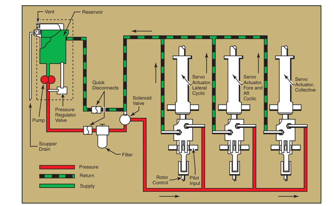
Walk up to almost any light aircraft and you will find at least one hydraulic system quietly doing its job. Hydraulic systems use an incompressible fluid under pressure to transmit force from one place to another — a principle that lets a pilot press a brake pedal with moderate foot pressure and generate enough clamping force to slow a two-thousand-pound aircraft. On more complex single-engine and light twin aircraft, that same principle extends to retracting landing gear and operating flaps. Understanding how these systems work, what their key components are, and how to recognize a malfunction will serve you both on the FAA knowledge test and in the cockpit.
The science behind every hydraulic system traces back to Pascal's Law: pressure applied to a confined, incompressible fluid is transmitted equally in all directions throughout the fluid. Because pressure equals force divided by area, a small force on a small piston can create an enormous force on a larger piston simply by making the output piston bigger. Light aircraft hydraulic systems exploit this relationship to trade mechanical advantage for movement — the output piston may move a shorter distance than the input piston, but the force it delivers is multiplied proportionally.
Core Components of a Hydraulic System
Even the simplest aircraft hydraulic system contains the same family of parts, and recognizing each one is essential for understanding how the whole system behaves.
- Reservoir: The reservoir stores hydraulic fluid and acts as the supply and return point for the entire system. It also allows fluid to expand as it heats up, and it provides a place for air bubbles to escape. Many light aircraft reservoirs are small, holding only a quart or two of fluid, and they are often translucent or have a sight glass so the pilot or mechanic can check the fluid level during preflight.
- Pump: The pump creates flow and thereby creates pressure. Light aircraft may use a hand pump (operated by the pilot for ground checks or as a backup), an electrically driven pump, or an engine-driven pump. The pump does not create pressure by itself — pressure builds when flow is restricted by a load, such as a landing gear actuator reaching the end of its travel.
- Selector Valve: The selector valve directs fluid to one side or the other of an actuating cylinder, controlling the direction of movement (gear up versus gear down, for example). The pilot's cockpit control — a landing gear handle or flap lever — is mechanically or electrically connected to this valve.
- Actuating Cylinder (Actuator): The actuator converts fluid pressure back into mechanical force and movement. A piston inside a sealed cylinder is pushed by pressurized fluid on one side, extending or retracting whatever component is attached. Single-acting actuators use fluid pressure in one direction and a spring to return; double-acting actuators use fluid pressure in both directions for positive movement in each direction.
- Relief Valve: Every hydraulic system must have a pressure relief valve to protect against over-pressurization. If pressure exceeds a preset limit — from thermal expansion, a blocked line, or a pump that keeps running — the relief valve opens and returns fluid to the reservoir. This is a critical safety device.
- Check Valve: A check valve allows fluid to flow in only one direction, preventing backflow that could allow a gear leg or other component to creep out of position.
- Hydraulic Lines and Fittings: Rigid metal tubing carries fluid throughout most of the system. Flexible hoses are used wherever movement between components requires it — for example, near the landing gear attachment point. Any crack, chafe, or leaking fitting is a serious concern because even a small leak reduces system pressure and can allow air into the lines.
- Hydraulic Fluid: The fluid itself is the medium that transmits force. Light aircraft typically use one of two types: MIL-PRF-5606 (a mineral-based red fluid) or MIL-PRF-87257 (a similar mineral-based fluid), or in some aircraft a vegetable-based blue fluid. These types are not interchangeable without manufacturer approval. Using the wrong fluid can cause seals to swell and fail. Always check the aircraft's Pilot's Operating Handbook (POH) and the placard on the reservoir for the correct specification.
Where Hydraulics Are Used in Light Aircraft
Brake Systems
The most universal hydraulic application in light aircraft is the wheel brake system. Each main gear wheel has a brake assembly — typically a disc brake on modern aircraft — with a hydraulic caliper that squeezes brake pads against a rotor. The pilot's rudder pedals each have a toe brake section at the top; pressing the toe brake pushes a master cylinder piston, pressurizing a small quantity of fluid and forcing the caliper closed. Because each main wheel has an independent circuit with its own master cylinder, the pilot can apply asymmetric braking to assist steering on the ground. A parking brake valve locks the system under pressure to hold the aircraft in place. A soft or spongy brake pedal is a classic sign that air has entered the brake lines, and that system must be bled by a mechanic before further flight.
Retractable Landing Gear
Most retractable-gear light aircraft use either a hydraulic system or an electric actuator system (or a combination) to raise and lower the gear. In a hydraulic gear system, a pump — often electrically driven and automatically controlled by the gear handle — pressurizes fluid to drive actuating cylinders that retract or extend each gear leg. Downlocks and uplocks are mechanical devices (sometimes hydraulically released) that lock the gear firmly in position and hold it there without continuous hydraulic pressure. This is important: if hydraulic pressure is lost with the gear up, the uplocks hold the gear in place. If pressure is lost with the gear down, the downlocks do the same. A critical backup is the emergency extension system — typically either a free-fall system (releasing the uplock so gravity and airloads extend the gear) or a hand pump that the pilot can use to build enough pressure to cycle the gear down manually.
Flap Systems
On some light aircraft, flaps are operated hydraulically rather than electrically or manually. A hydraulic flap system works similarly to the gear system: a selector sends pressurized fluid to actuating cylinders under each flap. Because fluid is incompressible, both flap panels move simultaneously and hold their position precisely, which is important for maintaining balanced lift. Most light trainers use electric or cable-driven flaps, so you are more likely to encounter hydraulic flaps on complex or high-performance singles and light twins.
Why Hydraulic System Knowledge Matters
System knowledge is not just an academic exercise — it directly affects decision-making during abnormal and emergency situations. A pilot who understands that a softening brake pedal means air in the lines will not try to pump the brakes back to normal and press on; instead, they will divert to a longer runway, plan for a possible runway excursion, and have the system inspected before the next flight. A pilot who knows the landing gear has an emergency hand pump will not panic at a gear-unsafe indication but will methodically work through the checklist. The FAA's Pilot's Handbook of Aeronautical Knowledge emphasizes that understanding aircraft systems enables better aeronautical decision-making (ADM) because you can anticipate failures, interpret indications correctly, and choose the right emergency response.
Key Numbers and Rules
- Hydraulic fluid types must not be mixed without manufacturer authorization — the wrong fluid can destroy rubber seals and render the entire system inoperative.
- Pascal's Law is the governing principle: pressure is equal throughout a confined incompressible fluid, allowing force multiplication based on piston area ratios.
- Relief valve protects the system from over-pressurization — it is not a normal operating valve and its opening indicates a problem.
- Spongy brakes indicate air in the hydraulic lines — air is compressible and absorbs pedal input instead of transmitting pressure to the calipers.
- Gear downlocks and uplocks hold the gear mechanically so that gear position is maintained without continuous hydraulic pressure.
- Emergency gear extension procedures are detailed in the aircraft's POH/AFM — the pilot must be thoroughly familiar with these before flying a retractable-gear aircraft.
- Preflight check: verify hydraulic fluid level (if accessible), inspect visible lines for leaks or chafing, and check brake pedal firmness during ground operations.
Common Test Traps
- Confusing hydraulic and pneumatic systems: Hydraulic systems use incompressible liquid; pneumatic systems use compressible gas (air or nitrogen). The key word in Pascal's Law is incompressible — this is why hydraulics can transmit force without loss due to compression.
- Assuming the pump creates pressure alone: The pump creates flow; pressure only builds when that flow is restricted. If you cycle a selector valve to extend gear and nothing is connected to restrict flow, pressure would not build.
- Wrong fluid type: FAA test questions sometimes ask what happens when incorrect hydraulic fluid is used. The answer involves seal degradation and system failure — not just reduced performance.
- Spongy vs. hard brakes: A spongy brake means air in the lines (air compresses). A hard brake that won't release may indicate a stuck caliper or a problem with the return path. Don't confuse the two scenarios.
- Thinking downlocks need pressure to hold: Mechanical downlocks hold the gear down without hydraulic pressure. The gear will not collapse simply because hydraulic pressure is lost — this is a common misconception that the FAA may test through scenario questions about partial hydraulic failure.