When an aviation maintenance technician inspects or overhauls a propeller, two fundamental concepts govern nearly every measurement taken: blade station and blade angle. A blade station is a specific location along the propeller blade, measured in inches from the center of the propeller hub. Blade angle — sometimes called pitch angle — is the angle between the chord line of the blade at a given station and the plane of rotation. Together, these two ideas form the backbone of propeller inspection, repair, and track-and-balance procedures covered in the FAA Aviation Maintenance Technician Handbook — Powerplant (FAA-H-8083-31).
Understanding why stations and angles matter requires a quick look at propeller geometry. A propeller blade is a rotating airfoil. Like a wing, its chord line and angle of attack determine how efficiently it converts engine torque into thrust. Because a blade is twisted from root to tip — with a high pitch angle near the hub and a much lower pitch angle near the tip — there is no single representative angle for the entire blade. Instead, manufacturers designate one or more reference stations where blade angle must fall within a specified tolerance for the propeller to be considered airworthy and performing as designed.
Understanding Blade Stations
A blade station is defined as the distance in inches from the center of the propeller hub to the measurement point on the blade. The center of the hub is station zero. As you move outward toward the blade tip, station numbers increase. For example, a station labeled "30" is located 30 inches from the hub center along the blade's longitudinal axis.
Manufacturers specify in their propeller service manuals which station or stations are used as the reference for blade angle measurement. The most commonly used reference station is 30 inches from the hub center for many general aviation propellers, though this varies by design and must always be confirmed in the applicable manufacturer's documentation or Type Certificate Data Sheet (TCDS). The 30-inch station is widely used because it represents a part of the blade where aerodynamic forces are significant and where twist has reached a representative mid-range value — making it a reliable indicator of overall pitch setting.
To locate a blade station precisely during inspection, the technician measures along the leading edge or the blade's flat face from the hub center (or the center of the propeller flange, depending on the manufacturer's instruction) to the specified station. Accurate measurement is essential; even a small error in station location translates directly into an erroneous blade angle reading.
How Blade Angle Is Measured
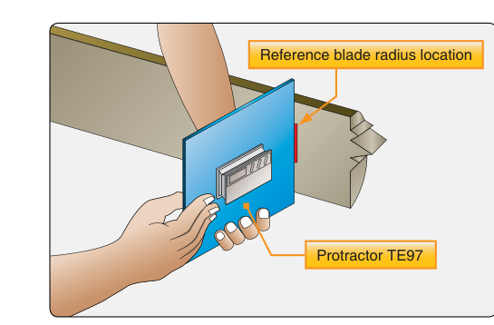
The tool of choice for blade angle measurement is the propeller protractor, also called a blade angle protractor or universal propeller protractor. The FAA-H-8083-31 describes the procedure in detail. The propeller protractor is a precision instrument that uses a spirit level and a rotating degree ring to measure the angle of the blade chord line relative to a reference plane — specifically, the plane of propeller rotation.
Step-by-Step Measurement Procedure
- Secure the aircraft. The airplane must be on level ground or the propeller must be mounted in a fixture. If measured on the aircraft, level the aircraft laterally and longitudinally using a spirit level and the aircraft's leveling means specified in the Type Certificate Data Sheet.
- Position the blade. Rotate the blade so that the face (flat side, or thrust face) is oriented in a convenient position for measurement — typically with the blade horizontal or positioned per the manufacturer's procedure.
- Set the protractor to zero relative to the plane of rotation. Place the protractor on the back face (cambered side) or flat face of the blade, depending on the design. Some manufacturers specify measuring on the flat face; others on the leading edge. Zero the protractor's degree ring by first placing it against a surface known to be in the plane of rotation (such as the propeller hub face or a leveled reference surface), then locking the ring at zero.
- Move the protractor to the specified station. Slide the protractor to the designated reference station (e.g., 30 inches) along the blade, keeping the baseline of the instrument in full contact with the blade surface.
- Read the angle. With the protractor positioned correctly at the station, read the degree scale. This reading is the blade angle at that station.
- Compare to manufacturer's limits. Look up the specified blade angle and allowable tolerance in the manufacturer's overhaul or service manual. A typical fixed-pitch propeller will have a very narrow tolerance — sometimes as tight as ±0.1° — between blades on the same hub. The overall blade angle setting must also fall within the range published in the TCDS.
Fixed-Pitch vs. Controllable-Pitch Considerations
For fixed-pitch propellers, the blade angle is set during manufacture and cannot be changed in the field. The technician's job is to verify that the blade angle at the reference station matches the approved value and that all blades on the same propeller hub are within the specified symmetry tolerance of each other. A difference in blade angle between blades causes vibration, uneven thrust, and accelerated structural stress.
For adjustable-pitch propellers (those where pitch can be set on the ground but not in flight) and controllable-pitch propellers (including constant-speed propellers), blade angle measurement is part of the rigging and adjustment process. The technician measures blade angle to confirm that each blade achieves the correct low-pitch (fine) and high-pitch (coarse) stops within published limits. These stops protect the engine from overspeeding at low pitch and from excessive load at high pitch. Both limits must be verified and documented.
Why Blade Angle Accuracy Matters
The consequences of an incorrect blade angle extend directly to flight safety and engine health. If a blade is set at too fine (low) an angle, the engine can overspeed because aerodynamic resistance on the blade is reduced. If the angle is too coarse (high), the engine may be overloaded — unable to reach proper RPM — resulting in reduced power output, poor acceleration, and potential detonation in piston engines. On multi-blade hubs, a difference in angle between blades creates an asymmetric thrust condition that manifests as propeller vibration, which accelerates fatigue cracking in the propeller hub, engine mounts, and airframe.
The FAA-H-8083-31 emphasizes that propeller vibration is one of the leading causes of in-service propeller and engine damage, and that proper blade angle setting and verification is a primary defense against it. This is why blade angle measurement is required after any repair that might alter blade geometry — including straightening a bent blade tip, applying a repair to the leading edge, or reinstalling blades on a controllable-pitch hub.
Key Numbers and Rules
- Station zero is at the center of the propeller hub; stations increase in inches toward the tip.
- The 30-inch station is the most common reference for general aviation propellers, but always verify with the manufacturer's data.
- Blade angle tolerance between blades on the same hub is often as tight as ±0.1° — confirm the exact figure in the applicable service manual.
- For fixed-pitch propellers, blade angle is set at the factory and verified — never adjusted — during maintenance.
- For constant-speed propellers, both low-pitch stop and high-pitch stop angles must be verified and fall within the ranges published in the TCDS and manufacturer's manual.
- The aircraft must be leveled per the TCDS before on-aircraft blade angle measurement; an unlevel aircraft introduces direct measurement error.
- All propeller repairs and blade angle checks must be documented in the aircraft and propeller maintenance records per 14 CFR Part 43.
Common Test Traps
- Confusing station zero with the blade root. Station zero is the center of the hub, not the root of the blade. The blade root sits outboard of center, so even station 6 or 8 inches may still be within the hub shank area.
- Assuming the same reference station for all propellers. While 30 inches is common, the only authoritative source is the manufacturer's service manual or the TCDS. Using the wrong station produces an incorrect angle reading regardless of measurement technique.
- Forgetting to level the aircraft first. On-aircraft measurements made without leveling the airframe introduce a systematic tilt error into every blade angle reading.
- Confusing blade face and blade back. The face (flat or thrust face) is the side that faces aft; the back (cambered side) faces forward. Placing the protractor on the wrong surface produces an error equal to the chord camber angle — a significant mistake.
- Neglecting symmetry tolerance between blades. A test question may ask what the maximum allowable difference in blade angle is between blades; the answer comes from the manufacturer's data, not a universal rule — but test items often expect you to know that even a fraction of a degree matters for vibration-free operation.