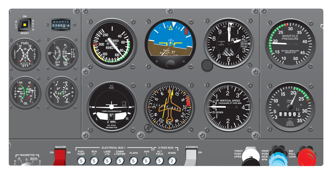
Among the most dangerous emergencies in instrument meteorological conditions (IMC) is the silent failure of the aircraft's vacuum system. Unlike an engine failure, which announces itself loudly and dramatically, a vacuum pump failure can go completely unnoticed for precious seconds or even minutes — long enough for a well-trained pilot to be seriously misled by slowly tumbling, apparently normal-looking gyroscopic instruments. Understanding how the vacuum system works, how its failure manifests, and exactly how to recover are not merely test topics: they are survival skills for any instrument-rated pilot.
This article covers the vacuum system's role in powering the primary gyroscopic flight instruments, the subtle and deceptive way failure presents itself, the standard recovery technique using partial-panel flying, and the key regulatory and practical considerations every instrument student must internalize.
How the Vacuum System Powers Your Gyroscopic Instruments
Most light general aviation aircraft use a engine-driven vacuum (or suction) pump to create a low-pressure airflow that spins the gyroscopes inside two critical instruments: the attitude indicator (AI) and the heading indicator (HI), sometimes called the directional gyro (DG). Air drawn through these instruments spins small gyroscope rotors at high speed — typically 10,000 to 15,000 RPM — and the gyroscopic rigidity in space that results provides the stable reference these instruments display.
The vacuum system consists of the engine-driven vacuum pump, an air filter, a pressure regulator, and a vacuum gauge (or suction gauge) on the instrument panel. The regulator maintains a specific suction level, usually around 4.5 to 5.5 inches of mercury (in. Hg) for most light aircraft, though always verify the specific aircraft's Pilot's Operating Handbook (POH) for the correct operating range. When suction is within the green arc on the gauge, the gyroscopes spin at design speed and the instruments are reliable.
It is important to understand that the turn coordinator (or older turn-and-slip indicator) is usually electrically powered, not vacuum-powered. This means it remains functional even when the vacuum system fails — a crucial fact for partial-panel flying. The magnetic compass is also fully independent of the vacuum system, relying only on Earth's magnetic field.
How Vacuum Failure Presents Itself
The insidious character of vacuum failure comes from the way gyroscopes behave as they lose power. They do not stop instantly. A spinning gyroscope with no driving force slowly winds down over several minutes, and during this spin-down period the gyro may precess unpredictably, causing the attitude indicator and heading indicator to drift gradually. The AI may show a slight bank or pitch that does not match reality — and because pilots are trained to trust their instruments over their physical sensations in IMC, they may follow the false indication right into a graveyard spiral or other unusual attitude.
The failure can be detected by cross-checking the vacuum/suction gauge. A reading below the green arc (or at zero) tells you immediately the pump has failed. However, many pilots do not scan the vacuum gauge frequently, and if they are task-saturated, the failing instruments may be the first clue. Signs that the vacuum system has failed or is failing include:
- The attitude indicator showing an unexpected or slowly increasing bank or pitch that does not correlate with what the turn coordinator, altimeter, airspeed indicator, and vertical speed indicator (VSI) are showing.
- The heading indicator slowly drifting in a way inconsistent with a coordinated flight path shown on the turn coordinator and compass.
- The vacuum gauge reading below the green arc or at zero.
- An annunciator light (on aircraft equipped with one) indicating low vacuum.
The golden rule of instrument flying applies here more than anywhere: always cross-check your instruments. No single instrument should be trusted without verification from the others. The attitude indicator is the primary culprit in vacuum failures because it is the dominant instrument in the scan; if it is presenting false information and goes unchallenged, spatial disorientation and loss of control can follow rapidly.
Recovery: Partial-Panel Flying
Once you suspect or confirm a vacuum failure in IMC, the recovery procedure has two immediate priorities: identify the failed instruments and transition your scan to the remaining reliable instruments. This is called flying partial panel — navigating without the attitude indicator and heading indicator, relying instead on the instruments that are still functioning.
Covering or Marking the Failed Instruments
Many experienced instructors and the Instrument Flying Handbook recommend physically covering the attitude indicator and heading indicator with instrument covers or sticky notes once failure is confirmed. This is more than a psychological crutch: it prevents your eye from being involuntarily drawn back to an instrument displaying false and misleading information. The human brain is highly pattern-oriented, and a convincing (but wrong) attitude display will continue to pull your attention unless you physically block it.
The Partial-Panel Instrument Scan
On partial panel, your primary references shift entirely to the pitot-static instruments — the altimeter, airspeed indicator, and VSI — and the electrically-powered turn coordinator. Bank control comes from the turn coordinator's miniature airplane wings: keep them level to maintain straight-and-level flight, or use a standard rate turn (needle deflected one width) to change heading. Pitch and power control come from the altimeter, airspeed indicator, and VSI working together.
For heading, you must now rely on the magnetic compass, which introduces its own challenge. The compass is subject to well-known errors — northerly turning error, acceleration error, and oscillation — that make it unreliable during banks and accelerations. To use it effectively on partial panel, you must apply the standard compass error corrections: for example, when turning to a northerly heading in the northern hemisphere, the compass lags behind the turn, so you must continue the turn and roll out after (undershoot) the desired heading; when turning to a southerly heading, the compass leads the turn, so you must roll out before reaching (overshoot) the desired heading. Practiced partial-panel flying requires knowing these compass behaviors cold.
Declaring an Emergency and Getting Help
A vacuum failure in IMC is an emergency. Under 14 CFR 91.3, the pilot-in-command has the authority and the responsibility to declare an emergency and deviate from any rule to meet that emergency. Declaring an emergency with ATC by squawking 7700 and communicating on 121.5 MHz (or your current frequency) immediately gets you radar identification, priority handling, and the guidance of approach controllers who can vector you to the nearest suitable airport for an immediate approach. Do not hesitate to declare. The practical benefit — vectors, sequencing priority, and a second set of eyes watching your radar return — can be life-saving.
Why This Matters: The Accident Record
The NTSB accident database contains a sobering number of fatal general aviation crashes attributed to vacuum system failures in IMC. The pattern is disturbingly consistent: the vacuum pump fails, the pilot does not notice (or notices too late), the attitude indicator slowly tumbles and presents false information, and the pilot enters a graveyard spiral — a progressively tightening, descending spiral that quickly exceeds the structural limits of the aircraft. The entire sequence from failure to loss of control can unfold in as little as two to three minutes if the pilot is not actively cross-checking the vacuum gauge and monitoring for instrument disagreement.
This is why the FAA and many flight schools strongly advocate for backup electrical gyroscopic instruments or modern Attitude and Heading Reference Systems (AHRS) that use solid-state sensors with no mechanical gyroscopes and no dependence on the vacuum system. Advisory Circular guidance and the Instrument Flying Handbook both discuss the value of backup systems, and AHRS-based glass cockpit displays have dramatically improved the safety margin for single-engine IFR flight.
Key Numbers and Rules
- Normal vacuum system operating range: approximately 4.5 to 5.5 in. Hg (confirm in your aircraft's POH).
- Instruments affected by vacuum failure: attitude indicator and heading indicator (gyro-driven by vacuum).
- Instruments NOT affected by vacuum failure: turn coordinator (usually electric), altimeter, airspeed indicator, VSI, magnetic compass.
- Emergency authority: 14 CFR 91.3 — PIC may deviate from any rule in an emergency.
- Emergency squawk code: 7700; emergency frequency: 121.5 MHz.
- Compass northerly turning error (northern hemisphere): compass lags when turning through north — roll out after (undershoot) the heading; compass leads when turning through south — roll out before (overshoot) the heading.
- Standard rate turn on partial panel: turn coordinator needle deflected one width, approximately 3° per second, completing a 360° turn in 2 minutes.
Memory Aid
When a vacuum failure is suspected, use the acronym C-I-C to structure your immediate response:
- C — Check: Confirm the vacuum gauge reads zero or below the green arc. Cross-check the AI and HI against the turn coordinator, altimeter, airspeed, and VSI for disagreement.
- I — Identify and isolate: Identify the failed instruments. Cover or mark the AI and HI to remove them from your scan.
- C — Control and communicate: Transition to partial-panel flying using the remaining reliable instruments, then declare an emergency and get ATC assistance immediately.
Common Test Traps
- Assuming the turn coordinator fails with the vacuum system. The turn coordinator is typically electrically powered and will remain operational — it is your primary bank reference on partial panel. The FAA knowledge test exploits this distinction frequently.
- Forgetting the vacuum gauge is in the scan. Test questions often describe a scenario where the AI and HI are behaving oddly and ask what the pilot should check first. The answer involves cross-checking the vacuum gauge and the other functioning instruments — not immediately trusting the AI.
- Misidentifying which compass errors apply during partial-panel turns. Remember: ANDS — Accelerate North, Decelerate South — describes the acceleration/deceleration error that occurs on east/west headings, which is separate from northerly turning error (compass lags on turns through north, leads on turns through south). These are tested in instrument scenarios involving compass use after vacuum failure.
- Delaying the emergency declaration. Some students hesitate because they want to be certain before declaring. In IMC on partial panel, certainty is a luxury you cannot afford. Declare first; you can always cancel the emergency if conditions improve.
- Continuing to scan the failed instruments. Even after confirming failure, pilots frequently glance back at the attitude indicator out of habit. The test may ask about the best practice to prevent this — the answer is to physically cover the failed instruments.