Walk into the cockpit of almost any single-engine trainer and you will find three round gauges that seem almost magical: they tell you which way is up, which way you are pointing, and whether you are turning — even when you cannot see the ground or horizon. These are the gyroscopic flight instruments, and in most light aircraft they are powered by a vacuum system that spins tiny gyroscopes at thousands of revolutions per minute. Understanding how the vacuum system generates that suction, how gyroscopes exploit the laws of physics, and — critically — how these instruments fail is essential knowledge for every private pilot, both for the FAA knowledge test and for real-world safety.
This article covers the three primary gyroscopic instruments found in most light aircraft, the vacuum (suction) system that drives them, the principles of gyroscopic rigidity and precession, and the common failure modes that have caught unprepared pilots off guard.
The Vacuum System: How Suction Is Created
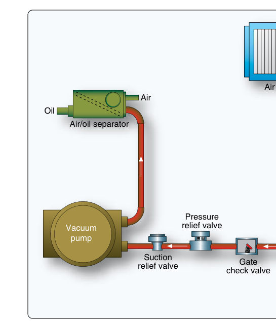
Most light aircraft use an engine-driven vacuum pump mounted on the accessory drive pad of the engine. This pump — typically a dry-air, carbon-vane type — creates suction by drawing air through a line connected to the instrument cluster. A vacuum regulator (suction relief valve) bleeds in ambient air to hold the suction level within the required range. A vacuum gauge on the instrument panel shows the pilot the current suction level, usually measured in inches of mercury (in. Hg).
Air does not flow directly into the gyroscopes; instead, filtered outside air is drawn through the gyroscopic instruments. As air rushes past small buckets or jets on the gyro rotors, it spins the rotors at high speed — typically between 15,000 and 18,000 RPM for attitude and heading indicators. The air then exits through the vacuum pump and is exhausted overboard. A vacuum filter prevents dust and debris from entering and contaminating the instruments; a clogged filter will reduce suction and slow the gyros.
The typical operating range for the vacuum system in most light aircraft is 4.5 to 5.5 inches of mercury, with many manufacturers specifying approximately 5 in. Hg as the target. If suction falls below the minimum, the gyros spin too slowly, causing instrument errors. If it is too high, internal components can be damaged. Pilots must check the vacuum gauge during the run-up and periodically in flight.
The Three Gyroscopic Flight Instruments
Attitude Indicator (AI)
The attitude indicator — also called the artificial horizon — uses a gyroscope whose spin axis is maintained vertical by the action of the vacuum system and small erecting mechanisms. Because of gyroscopic rigidity (explained below), the rotor resists any change to its orientation in space, so the instrument's horizon bar remains fixed relative to the true horizon while the aircraft (and its instrument case) pitches and banks around it. The AI gives the pilot an immediate, intuitive picture of the aircraft's pitch and bank attitude and is arguably the most important instrument in the cockpit during IMC.
The attitude indicator has known limitations: during prolonged coordinated turns, small erection mechanisms can cause the gyro to precess slightly, creating a false bank reading of up to 5° at the completion of a 180° turn. More importantly, it is subject to tumbling if the aircraft exceeds the instrument's pitch and bank limits (often ±60° of pitch and ±100° of bank), after which it must be re-erected before it reads accurately again.
Heading Indicator (HI) / Directional Gyro (DG)
The heading indicator (sometimes called the directional gyro) uses a gyroscope whose spin axis is maintained horizontal, providing a stable heading reference that is far easier to read in turbulence than a magnetic compass. Because the magnetic compass is subject to oscillation errors during turns and acceleration, pilots set the heading indicator to agree with the compass in straight-and-level, unaccelerated flight and then navigate primarily using the HI.
The heading indicator has one critical quirk: it does not sense the Earth's magnetic field. It is purely mechanical, so it drifts over time due to gyroscopic precession caused by bearing friction and the rotation of the Earth itself. Pilots must re-align the HI to the magnetic compass approximately every 15 minutes (or as recommended by the manufacturer) during cruise flight. Failure to do so can result in significant navigational errors.
Turn Coordinator (TC) and Turn-and-Slip Indicator
The turn coordinator uses a gyroscope mounted on a canted axis (tilted approximately 30° from the horizontal) so that it senses both roll rate and yaw rate. Its miniature aircraft symbol indicates the rate of turn: when the wing of the miniature airplane aligns with the "2 MIN" mark, the aircraft is executing a standard-rate turn of 3° per second, which will complete a 360° turn in exactly two minutes. Many aircraft also have a 1-minute mark for faster jets, but in light aircraft the standard is always the 2-minute reference.
The inclinometer (ball) at the bottom of the turn coordinator is not gyroscopic — it is a simple curved glass tube filled with liquid containing a steel ball. It shows whether the aircraft is in coordinated flight (ball centered), a slip (ball toward the low wing, inside of turn), or a skid (ball toward the outside of the turn). The memory phrase is "step on the ball": if the ball is displaced to the right, apply right rudder to center it.
Unlike the AI and HI, the turn coordinator is typically powered by the aircraft's electrical system, not the vacuum system. This is a deliberate design choice: if the vacuum pump fails, the pilot loses the AI and HI but retains the turn coordinator as a backup for controlling bank angle. This redundancy is important — recognize it on the test.
The Principles Behind Gyroscopic Instruments
Gyroscopic rigidity in space (also called gyroscopic inertia) is the tendency of a spinning mass to maintain its orientation in space regardless of how the mounting frame around it is moved. The faster the rotor spins and the greater its mass, the stronger this rigidity. It is this property that allows the attitude indicator to keep its horizon bar stable as the airplane pitches and rolls.
Precession is the second key principle: when a force is applied to the rim of a spinning gyroscope, the gyro does not react immediately in the direction of that force. Instead, it reacts 90° later in the direction of rotation. In flight instruments, precession is mostly a nuisance — it causes the heading indicator to drift and the attitude indicator to show small errors in prolonged turns. Understanding precession helps pilots anticipate and correct for these errors.
Why It Matters: Vacuum Failure In Flight
A vacuum pump failure in IMC is one of the most serious emergencies a pilot can face, and it is notoriously insidious. When the pump fails, the gyros do not stop immediately — they slowly spin down over several minutes. During this time, the instruments may show incorrect but plausible readings, tempting a pilot to trust them. This is called subtle instrument failure, and it is far more dangerous than an abrupt failure because the pilot may not recognize the problem until spatial disorientation has taken hold.
The best defense is to monitor the vacuum gauge constantly and immediately cross-check all instruments if an unusual reading appears on any gyroscopic instrument. Remember: the turn coordinator (electrically powered) and the magnetic compass remain valid after vacuum failure and can be used to maintain controlled flight while returning to VMC or executing an instrument approach using partial panel techniques.
Key Numbers and Rules
- Vacuum system normal range: approximately 4.5 to 5.5 in. Hg (check the specific POH for your aircraft).
- Gyro rotor speed: typically 15,000–18,000 RPM under normal suction.
- Standard-rate turn: 3° per second; completes 360° in 2 minutes; miniature aircraft aligns with the 2-MIN index.
- Heading indicator drift: must be realigned to magnetic compass approximately every 15 minutes.
- AI tumble limits: typically ±60° pitch, ±100° bank — exceeding these limits renders the instrument unreliable until re-erected.
- Turn coordinator power source: electrical (not vacuum) — survives vacuum pump failure.
- Attitude indicator and heading indicator power source: vacuum system (most light aircraft).
Memory Aid
"AH-Head needs Vacuum; TC uses Electric" — the Attitude indicator and Heading indicator ("AH-Head") are vacuum-powered; the Turn Coordinator uses electrical power. This reminds you of the backup you retain after a vacuum failure.
Common Test Traps
- Confusing which instrument uses which power source. The FAA loves to ask whether the turn coordinator is vacuum or electrically powered. It is electric; the AI and HI are vacuum-powered in most light aircraft.
- Misidentifying the inclinometer as gyroscopic. The ball (inclinometer) is NOT a gyroscopic instrument — it is a simple gravity/inertia device. Only the gyro rotor portion of the turn coordinator is gyroscopic.
- Forgetting that heading indicator drift is normal. The HI must be re-set regularly because it does not sense magnetic north. Confusing HI drift with compass error is a frequent mistake.
- Assuming vacuum failure is immediately obvious. When the vacuum pump fails, gyros spin down gradually. The instruments may look normal for several minutes. The vacuum gauge is your first warning — check it often.
- Mixing up slip and skid. In a slip, the ball deflects toward the inside (low wing) of the turn; in a skid, it deflects toward the outside. Always "step on the ball" — apply rudder in the direction the ball has moved to center it.