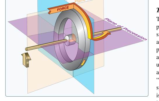
The directional gyroscope, often called the heading indicator or directional gyro (DG), is one of the most important attitude and navigation instruments in the cockpit. Unlike the magnetic compass, which is subject to turning errors, acceleration errors, and oscillation, the directional gyro provides a smooth and immediately responsive heading reference. However, the gyro does not sense magnetic north on its own — it simply maintains a fixed orientation in space through gyroscopic rigidity. Over time, the instrument's indicated heading creeps away from the actual magnetic heading through a phenomenon called precession and drift. Understanding the physics behind this drift, recognizing its causes, and knowing how to correct it are essential knowledge for both the FAA Airframe knowledge test and safe aircraft maintenance practice.
This article covers the mechanical principles of gyroscopic precession, the specific sources of drift in a directional gyro, published correction intervals, and the maintenance technician's role in inspecting and servicing these instruments.
Gyroscopic Rigidity and the Basis of the Directional Gyro
A spinning gyroscope exhibits two fundamental properties: rigidity in space and precession. Rigidity in space means that once a gyro's rotor is spinning at high speed, it resists any force that tries to change the orientation of its spin axis. This property is what makes the directional gyro useful — mount a spinning rotor in a set of gimbals, align its case to a known heading, and it will hold that reference while the aircraft turns around it.
The rotor of a typical air-driven directional gyro spins at approximately 10,000 to 18,000 RPM. Pneumatic gyros are driven by air from either a vacuum pump system (suction) or a pressure pump system, routed through a filter and then through jets inside the gyro housing that impinge on buckets around the rotor rim. Electric gyros use a brushless AC or DC motor and can achieve even higher rotor speeds, which improves rigidity and reduces drift.
The gimbals provide the freedom of movement that allows the instrument case (and therefore the aircraft) to rotate while the rotor stays fixed. A directional gyro has two gimbals, giving it two degrees of freedom in addition to the spin axis. This configuration allows it to measure yaw (heading changes) while the rotor remains oriented.
Precession: The Core Physics of Drift
Precession is the tendency of a gyroscope to respond to an applied force not where the force is applied, but 90 degrees further in the direction of rotor rotation. In an ideal, frictionless gyro in a frictionless environment, no precession would occur spontaneously — the rotor would maintain its orientation indefinitely. In the real world, precession is the underlying mechanism by which all forms of gyro drift occur, because any small unwanted torque acting on the rotor will cause the gyro to precess away from its correct orientation.
Think of it this way: bearing friction in the gimbal pivots creates tiny, constant torques. Each of those torques causes the gyro to precess — to drift — slowly but continuously. The direction and rate of drift from bearing friction can be somewhat random and varies from instrument to instrument, which is one reason manufacturers specify maximum allowable drift rates.
Sources of Directional Gyro Drift
Drift in a directional gyro comes from two broad categories of sources: apparent drift (caused by the Earth's rotation and the aircraft's own movement over the curved Earth) and real drift (caused by mechanical imperfections within the instrument itself).
Apparent Drift Due to Earth's Rotation
Because the gyro maintains its orientation relative to inertial space — not relative to the rotating Earth — Earth's rotation slowly causes the geographic reference frame to rotate under the gyro. This creates an apparent change in indicated heading even if the gyro were mechanically perfect. The rate of this apparent drift depends on latitude. At the equator, the component of Earth's rotation that affects a horizontal gyro is zero; at the poles, it reaches its maximum of approximately 15 degrees per hour (Earth rotates 360 degrees in 24 hours). At mid-latitudes typical of continental U.S. operations, the apparent drift rate due to Earth's rotation is in the range of several degrees per hour.
Apparent Transport Drift
As an aircraft flies over a curved Earth, its position relative to the meridians of longitude changes. A gyro that was aligned to a meridian at the departure point will show a slight error relative to the new local meridian at the destination. This is called transport wander. For general aviation aircraft flying relatively short distances and at relatively slow speeds, transport wander is small compared to mechanical drift but becomes more significant for high-speed, long-range operations.
Real Drift Due to Mechanical Imperfection
Real drift is caused by imperfections in the physical instrument: bearing friction in the gimbal pivots, gimbal imbalance, rotor imbalance, and air turbulence inside the housing of pneumatic gyros. These mechanical factors continuously apply small random torques to the rotor, each of which causes precession and therefore drift. An airworthy pneumatic directional gyro is typically expected to drift no more than 3 degrees in 15 minutes under normal operating conditions, though manufacturers' specifications vary. An instrument that drifts significantly more than this is a candidate for overhaul or replacement.
Vacuum System Pressure Effects
Air-driven gyros are sensitive to the vacuum or pressure level driving the rotor. If suction falls below the required range — typically 4.5 to 5.5 inches of mercury for most general aviation aircraft, though this varies by aircraft and instrument — the rotor spins too slowly, rigidity decreases, and drift rates increase noticeably. Conversely, excessive suction can cause wear on the rotor bearings and reduce instrument life. The AMT must ensure the vacuum system is rigged to the manufacturer's specified range.
Correcting for Drift: The Pilot's Role
Because drift is unavoidable, directional gyros are designed with a manual setting knob that allows the pilot to realign the instrument to the magnetic compass. The standard procedure is to align the DG to the magnetic compass every 10 to 15 minutes during straight and level, unaccelerated flight — conditions under which the magnetic compass is most accurate and least subject to its own errors. During turns or acceleration, the magnetic compass should not be used as the reference for resetting the DG.
Slaved gyroscope systems, found in more sophisticated aircraft, use a flux gate compass (a remote-sensing magnetic heading detector) to continuously and automatically correct the directional gyro for drift. The flux gate senses the horizontal component of Earth's magnetic field and feeds a correction signal to a slaving mechanism that slowly and continuously nudges the gyro back into alignment. The rate of slaving correction is intentionally slow so that the instrument does not respond to short-term magnetic disturbances or turning errors.
Why Drift Correction Matters: Safety and Airworthiness
Accumulated directional gyro drift poses a direct navigational hazard. A pilot who fails to periodically reset the DG may be navigating on a heading that is 10 or more degrees off from the intended course, a significant error over any appreciable distance. In instrument meteorological conditions (IMC), an undetected heading error can lead to controlled flight toward terrain, airspace violations, or departure from an instrument approach path.
From the airframe technician's perspective, excessive drift is a symptom of a worn or failing instrument, an inadequate vacuum system, or a contaminated gyro filter. During an annual inspection or 100-hour inspection, the technician must verify the condition and operation of all gyroscopic instruments, check vacuum system pressure, replace the air filter per the manufacturer's schedule, and note any reported excessive drift from the pilot's discrepancy log.
Key Numbers and Rules
- Maximum allowable drift: Typically no more than 3 degrees in 15 minutes for an airworthy pneumatic directional gyro; always verify the specific aircraft's POH and instrument manufacturer data.
- Typical vacuum system range: 4.5 to 5.5 inches of mercury suction (verify manufacturer's specification for the specific aircraft).
- Earth's rotation rate: 15 degrees per hour; at mid-latitudes, this contributes several degrees per hour of apparent drift even in a perfect gyro.
- Pilot realignment interval: Every 10 to 15 minutes in straight and level, unaccelerated flight, referencing the magnetic compass.
- Precession rule: An applied force to a gyro rotor causes a reaction 90 degrees ahead in the direction of rotor rotation.
- Slaved gyros: Use a flux gate sensor to automatically and continuously correct drift; correction rate is intentionally slow to avoid responding to momentary magnetic anomalies.
Common Test Traps
- Confusing real and apparent drift: Real drift comes from mechanical imperfections inside the instrument. Apparent drift comes from Earth's rotation and aircraft transport over the curved Earth — it would occur even in a mechanically perfect gyro.
- Misidentifying when to reset the DG: The DG should only be reset to the magnetic compass during straight, level, unaccelerated flight. Resetting during a turn or while accelerating will introduce the same errors that affect the magnetic compass (northerly turning error, acceleration error) into the directional gyro.
- Assuming the DG is self-correcting: A conventional (unslaved) directional gyro has no automatic mechanism to detect or correct drift. Only a slaved gyro system with a flux gate provides continuous automatic correction.
- Ignoring vacuum pressure as a drift cause: Low vacuum reduces rotor RPM and rigidity, dramatically increasing drift. A suddenly drifting DG should prompt the pilot and technician to check the vacuum gauge and pump immediately.
- Misapplying the precession direction: The FAA knowledge test often presents scenarios requiring the applicant to predict which direction a gyro will precess when a force is applied. Remember: the gyro reacts as if the force were applied 90 degrees further in the direction of rotation, not at the actual point of application.