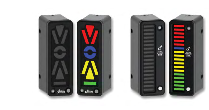
Of all the aerodynamic concepts a pilot or technician must understand, angle of attack (AOA) is arguably the most fundamental to safe flight. Unlike airspeed, which only indirectly reflects how close an aircraft is to a stall, the angle of attack tells the wing's story directly — it measures the actual angle between the chord line of the wing and the oncoming relative wind. When that angle exceeds a critical value, the wing stalls, regardless of how fast or slow the aircraft is flying, how heavy it is, or how steeply it is banked. The AOA indicator system brings this critical parameter into the cockpit in real time, and installing one correctly is both a regulatory exercise and a precision mechanical task that every airframe technician must understand thoroughly.
The FAA has actively encouraged the adoption of AOA indicator systems in general aviation through its safety initiatives, recognizing that loss of control — often preceded by an inadvertent stall — remains a leading cause of fatal accidents. Understanding the system's components, how they sense airflow, how they are installed per regulatory and manufacturer requirements, and how they are tested for proper operation is essential knowledge for any AMT working on aircraft instrument systems.
How the System Works
An AOA indicator system measures the angle between the aircraft's chord line and the relative wind by sensing differential air pressure or by detecting the physical position of a vane that aligns itself with the local airflow. There are two dominant sensing technologies used in certificated general aviation installations:
- Differential pressure (pneumatic) sensors: These use a probe — often called a balanced pressure or slotted probe — mounted flush or near-flush on the fuselage or wing leading edge. The probe has two or more orifices positioned at specific angles to the airstream. As AOA changes, the relative amount of stagnation pressure entering each orifice changes. The system compares these pressures and converts the differential into an AOA reading. The probe must be located where local airflow accurately represents the free-stream angle of attack, typically on the forward fuselage or wing leading edge where it is clear of propeller wash and airframe disruption.
- Mechanical vane sensors: A small aerodynamic vane, much like a wind-vane, is mounted externally and free to rotate about a horizontal axis. It continuously aligns with the local relative wind. A precision potentiometer or synchro transducer converts the vane's angular position into an electrical signal sent to the indicator. Vane-type sensors must be positioned carefully so the vane's movement range covers the full AOA envelope of the aircraft without mechanical binding.
Inside the cockpit, the indicator translates the sensor signal into a visual display. This may be a traditional needle-and-arc gauge, a series of colored LEDs (green for cruise, yellow for approach, red for approaching critical AOA, and a flashing or solid indication at or near stall AOA), or a digital display integrated into a glass cockpit. Some systems also drive an aural tone or voice warning as AOA increases toward the critical value. The critical AOA — the angle at which the wing will stall — is a fixed aerodynamic property of the wing's airfoil shape, independent of weight and load factor, which is why the AOA indicator provides stall warning margin that a simple airspeed indicator cannot replicate.
Regulatory Framework for Installation
Installing an AOA indicator system on a certificated aircraft is a significant maintenance action governed by 14 CFR Part 43 and the aircraft's type design. The technician must determine the appropriate approval path before any installation begins. FAA Advisory Circular guidance has recognized several pathways for general aviation AOA installations:
- Supplemental Type Certificate (STC): Many commercial AOA systems are sold with an approved STC, which covers specific aircraft makes and models. The STC data package includes the installation instructions, wiring diagrams, weight and balance effects, flight manual supplement, and any required placard information. The AMT must follow the STC holder's instructions precisely — deviating from the approved data invalidates the approval.
- Field Approval (FAA Form 337): For installations not covered by an existing STC, the installer may seek a field approval from the local Flight Standards District Office (FSDO). The installer must prepare engineering data demonstrating the installation does not adversely affect the aircraft's airworthiness, including structural analysis for any new penetrations and verification that the sensor location provides accurate AOA data.
- CAA / ASTM standards for Light Sport Aircraft: Aircraft certificated under the Light Sport category follow ASTM consensus standards, and AOA system installations may be accomplished by a Repairman (Light Sport Aircraft) certificate holder following manufacturer maintenance instructions.
Regardless of approval path, 14 CFR Part 43 requires that all maintenance be recorded in the aircraft maintenance records with a description of the work performed, the date, and the signature and certificate number of the person approving the work for return to service. A weight and balance update is required whenever equipment is added or relocated.
Installation Procedure
While specific steps vary by system and aircraft, the general installation sequence follows a logical order that protects both the aircraft and the accuracy of the finished system.
Sensor Placement and Mounting
The sensor — whether a differential pressure probe or a vane — must be positioned per the approved data. For a fuselage-mounted probe, this typically means a location on the forward fuselage below the cockpit, on the aircraft centerline or near-symmetrical position, away from aerodynamic shadows and ahead of any landing gear doors or antennas that could disturb airflow. The probe must be oriented precisely in the aircraft's plane of symmetry (or per the manufacturer's specified lateral offset and angular alignment). Drilling fuselage skin for a flush probe requires careful use of a unibit or step drill, followed by deburring to prevent stress risers. The mounting flange is typically sealed with approved sealant to prevent moisture ingress into the airframe structure.
For a vane sensor, the mounting bracket must allow the vane its full rotational travel as specified by the manufacturer's or STC installation data, without contacting any adjacent structure. The vane pivot must be checked for free, smooth movement with no stiction or binding, since any resistance introduces measurement error at low airspeeds when the aerodynamic torque on the vane is smallest.
Plumbing and Wiring
Pneumatic lines from a differential pressure probe must use tubing of the type and diameter specified by the manufacturer, properly supported and secured to prevent chafing. All fittings must be leak-checked after installation. Electrical wiring for vane-type or electrically-transmitting pressure systems must be routed per the aircraft's existing wire bundle standards — supported at intervals per AC 43.13-1B guidance (which varies by wire size and routing, with tighter spacing near connectors or in areas of vibration), protected from heat sources, separated from high-current buses, and terminated with the connector types specified in the installation data. Shielded cable is often required to prevent electromagnetic interference from distorting the low-level sensor signal.
Cockpit Indicator Installation
The cockpit indicator is typically mounted in the instrument panel using the standard 2.25-inch or 3.125-inch round instrument cutout, or via a dedicated bracket per the STC. The installer must verify panel thickness compatibility and use appropriate hardware. Backlight wiring is connected to the aircraft's panel lighting bus, and power and ground connections are made per the wiring diagram. A properly labeled circuit breaker must be installed or an existing breaker of the correct amperage identified per the approved data.
System Testing and Calibration
After installation, the system must be tested before the aircraft is returned to service. The technician performs a ground functional test by manually deflecting the vane (or applying differential pressure to the probe ports) through its full range and verifying that the cockpit indicator responds correctly and in the proper direction — increasing AOA must produce a reading that progresses toward the warning zone, not away from it. Any aural warning must activate at the AOA specified in the STC or installation data.
For pneumatic systems, a leak check of all plumbing is mandatory. Many systems require an in-flight calibration or confirmation flight, often performed by a certificated pilot, to verify that the system's stall indication correlates with the aircraft's actual stall behavior. The results of the calibration flight and any adjustments made are recorded in the maintenance records. The approved Rotorcraft or Airplane Flight Manual Supplement (AFMS) provided with the STC must be placed in the aircraft's permanent records and made accessible to the flight crew.
Why It Matters
From a safety standpoint, the AOA indicator gives the pilot a direct window into the wing's aerodynamic margin — something that airspeed alone cannot provide. A heavily loaded aircraft stalls at a higher airspeed than a lightly loaded one, but both stall at the same critical AOA. Similarly, in a steep banked turn where load factor is elevated, the stall speed rises sharply, yet the critical AOA remains constant. A properly installed AOA system warns the pilot regardless of weight, configuration, or bank angle. For the AMT, a faulty installation — a misaligned probe, a kinked pneumatic line, a reversed electrical connection — can give the pilot a dangerously misleading indication or no warning at all. Installation precision is therefore a direct flight safety issue, not merely a regulatory checkbox.
Key Numbers and Rules
- Critical AOA: Fixed for a given airfoil; commonly cited FAA training material places it in roughly the mid-teens to around 20 degrees for most general aviation airfoils, though the exact value is airfoil-specific and established by the manufacturer.
- 14 CFR Part 43: Governs all maintenance, preventive maintenance, rebuilding, and alteration; the AOA installation must be recorded per §43.9, which covers content, form, and disposition of maintenance and alteration records.
- Weight and balance update: Required any time equipment mass or arm changes, per 14 CFR Part 43 Appendix A and associated maintenance recordkeeping requirements; the AOA system's actual weight and arm — as documented in the STC or installation data — must be recorded.
- Wire support intervals: Per AC 43.13-1B Chapter 11 (the FAA's accepted maintenance practices document), wire bundle support spacing depends on wire size and routing, with guidance up to 24 inches and tighter spacing required near connectors or in areas of vibration; wiring must be protected from abrasion and heat.
- Return to service: Requires signature, certificate number, date, and description per 14 CFR §43.9; the AFMS must be placed in the aircraft.
Common Test Traps
- Confusing AOA with pitch attitude: AOA is the angle between the chord line and the relative wind, not the horizon. An aircraft in a nose-low dive can still have a high AOA if the relative wind is angled steeply upward relative to the wing — this distinction is frequently tested.
- Assuming airspeed determines stall: Stall occurs at a critical AOA, not a fixed airspeed. Weight, load factor, and configuration all shift the stall speed, but the critical AOA stays constant for a given airfoil — the whole point of the AOA indicator.
- Overlooking the AFMS requirement: An STC installation is not complete until the Flight Manual Supplement is placed in the aircraft. Forgetting this step means the aircraft is not airworthy for return to service.
- Vane binding: A vane sensor that binds or sticks will produce a frozen or sluggish AOA reading. Technicians must verify full, free vane travel during installation and after any paint or sealant application near the sensor.
- Incorrect probe orientation: A differential pressure probe installed rotated 180 degrees will produce reversed indications — showing low AOA when the aircraft is near stall. Always verify probe orientation markings before finalizing the installation.