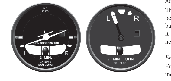
Walk into any general aviation cockpit and you will likely find a small round instrument showing either a miniature airplane symbol or a needle pointer, paired with a ball in a curved glass tube. These two instruments — the turn coordinator and the older turn-and-slip indicator (sometimes called the turn-and-bank indicator) — serve related but distinct purposes. Both help a pilot maintain coordinated flight and execute standard-rate turns, yet their internal construction, the axes of motion they sense, and the information they display are meaningfully different. For an Aviation Maintenance Technician (AMT) working on airframe instrument systems, understanding these differences is essential not only for the FAA knowledge test but also for correctly inspecting, bench-testing, and replacing these instruments in service.
Although modern glass-panel aircraft have largely replaced these gyroscopic instruments with solid-state attitude and heading reference systems (AHRS), the underlying principles remain foundational. Legacy aircraft and many training fleets still rely on vacuum- or electrically-driven gyroscopic instruments, making a thorough understanding of their design and operation a day-to-day maintenance reality.
How Gyroscopic Instruments Work — A Quick Foundation
Both instruments exploit the property of gyroscopic rigidity (rigidity in space): a spinning mass resists any force that tries to change the orientation of its spin axis. When a force is applied to a gyroscope, it reacts in a direction 90 degrees from the applied force along the plane of rotation — this is precession. The instrument designer uses precession to convert aircraft rotation into a measurable deflection of a pointer or symbolic display.
The critical difference between the two instruments starts at the gyro itself: specifically, the angle at which the gyro's spin axis is mounted inside the instrument case.
The Turn-and-Slip Indicator
The turn-and-slip indicator (T&S) uses a gyroscope whose spin axis is mounted horizontally, oriented parallel to the aircraft's lateral (wingtip-to-wingtip) axis. This geometry means the gyro is sensitive only to rotation about the aircraft's vertical axis — in other words, pure yaw. Roll movements are not sensed directly; the gyro simply does not precess in response to a pure rolling motion.
When the aircraft yaws — as in a coordinated turn — the gyro precesses and deflects a pointer (a vertical needle) left or right on the instrument face. The scale is calibrated so that a full needle deflection to the index mark indicates a standard-rate turn of 3 degrees per second, which completes a 360-degree turn in exactly two minutes. This is commonly called a two-minute turn or Rate 1 turn.
Beneath the needle (or in a separate curved tube) sits the inclinometer — the ball in the curved glass tube filled with damping fluid. The ball responds to the balance between gravitational and centrifugal forces. When the ball is centered, the forces are in balance and the turn is coordinated. When the ball is displaced toward the inside of the turn, the aircraft is in a slip; when displaced toward the outside, the aircraft is in a skid. The inclinometer is purely mechanical — it contains no gyroscope and is independent of the rest of the instrument.
The Turn Coordinator
The turn coordinator (TC) uses a gyroscope whose spin axis is canted, typically approximately 30 degrees upward from the horizontal toward the aircraft's longitudinal axis. This tilt is the single most important design distinction between the two instruments. Because of this cant, the gyro now responds to rotation about two axes simultaneously: the vertical (yaw) axis and the longitudinal (roll) axis.
This dual-axis sensitivity means the turn coordinator reacts to roll rate as well as yaw rate. In practical terms, the instrument deflects immediately as the pilot begins banking the aircraft — before a significant yaw rate has even developed — providing an earlier indication that a turn is being initiated. Once the aircraft settles into a stabilized bank and the roll rate drops to zero, the instrument responds only to the ongoing yaw rate of the turn, just like a T&S indicator.
The display uses a miniature airplane symbol (a stylized airplane silhouette, typically depicted as viewed from behind) instead of a needle. When the wing of the miniature airplane aligns with the turn index marks on the instrument face, the aircraft is in a standard-rate (Rate 1) turn. Like the T&S, the inclinometer ball assembly is mounted separately below the gyro mechanism and serves the same coordination function.
A critical fact that catches many students: the turn coordinator does NOT display bank angle. The miniature airplane wings do not indicate how steeply the aircraft is banked in degrees — they only indicate the rate of turn. A common misconception is that the symbol works like the attitude indicator's bank scale. It does not. The attitude indicator is the correct instrument for bank angle reference.
Gyro Power Sources
Both instruments can be driven by vacuum (suction) or by electrical power, and the power source is a major maintenance consideration. Many aircraft use the turn coordinator as the electrically-driven backup gyro instrument, deliberately powered from a different source than the vacuum-driven attitude and heading indicators. This redundancy means that if the vacuum system fails, the pilot retains at least one gyroscopic reference for turn-rate and roll-rate information — the turn coordinator. Note that the turn coordinator does not provide attitude (pitch and bank angle) information the way the attitude indicator does; it remains a backup source for rate-of-turn and coordination data, not a substitute attitude reference. The T&S indicator can be either vacuum or electric depending on the installation. AMTs must verify the power source type and ensure proper wiring or plumbing connections during installation or replacement, referencing the aircraft's maintenance manual and wiring diagrams.
Why It Matters — Maintenance and Safety Implications
From a maintenance standpoint, these differences have direct practical consequences. Because the gyro in a turn coordinator is canted, its gimbal stops and freedom-of-movement limits differ from those of the T&S. If an AMT inadvertently installs a T&S indicator in a panel position designed for a turn coordinator (or vice versa), the cockpit display will be physically different and the pilot will not receive the early roll-rate indication the aircraft design intended. Beyond cosmetics, this could constitute an unapproved alteration of the instrument system if done without proper data.
Both instruments rely on gyro spin-up to rated RPM before their indications are reliable. A common maintenance check is verifying the gyro erects and reaches operating speed within the time specified in the manufacturer's data. Sluggish erection, noise during spin-up, or failure to reach rated RPM are all signs of bearing wear or contamination. For vacuum-driven versions, the AMT must also verify suction is within the instrument manufacturer's specified range — typically checked with a suction gauge at the instrument panel.
Key Numbers and Rules
- Standard-rate (Rate 1) turn: 3 degrees per second, completing 360 degrees in 2 minutes — calibrated deflection on both instruments.
- Turn coordinator gyro cant angle: approximately 30 degrees from horizontal toward the longitudinal axis, enabling roll-rate sensing.
- Turn-and-slip gyro orientation: horizontal spin axis, sensing yaw only.
- Inclinometer fluid: a liquid-damped ball (usually in kerosene or similar fluid) — purely mechanical, not gyroscopic.
- Typical electric gyro voltage: commonly 14V DC or 28V DC in general aviation aircraft, but this varies by installation — always verify with the instrument's nameplate data and the aircraft's electrical system documentation.
- Vacuum-driven instruments: many light aircraft systems are commonly cited in the 4.5 to 5.5 inches of mercury suction range, but this figure varies by installation — always confirm with the specific manufacturer's and aircraft maintenance manual data.
- Turn coordinator does NOT show bank angle — only rate of turn and (initially) rate of roll.
Common Test Traps
- Confusing sensing axes: The FAA knowledge test frequently asks which axis each instrument senses. Remember: T&S senses yaw only (horizontal gyro); turn coordinator senses both roll rate and yaw rate (canted gyro).
- Miniature airplane = bank angle? No. A very common distractor. The miniature airplane indicates rate of turn, not the degree of bank. For bank angle, you look at the attitude indicator.
- Inclinometer is not gyroscopic: Questions may imply the ball uses a gyro. It does not — it is a purely gravitational/centrifugal balance device and will work even with a failed gyro.
- Power source mix-up: Test questions may ask why the turn coordinator is often electrically powered when attitude and heading indicators are vacuum-driven. The answer is redundancy — different power sources ensure at least one gyro survives a single system failure.
- Interchangeability: The two instruments are not interchangeable without proper maintenance data. Different gyro geometry, different displays, and potentially different power sources mean a replacement must match the approved instrument specification for that installation.
Putting It All Together
The turn-and-slip indicator and the turn coordinator both tell the pilot whether a turn is being made at standard rate and whether it is coordinated, but they achieve this through different gyro geometries that give them different sensitivities. The T&S uses a purely horizontal gyro axis to sense yaw alone, while the turn coordinator's canted gyro adds early roll-rate sensing, providing a quicker initial indication as a bank begins. For the AMT, recognizing these mechanical differences guides correct installation, troubleshooting, and replacement decisions. For the student pilot or instrument-rated aviator, understanding the distinction prevents dangerous misinterpretation of cockpit indications — particularly the critical point that neither instrument substitutes for an attitude indicator when determining actual bank angle.